20
Installation Product Manual - Perma-Cyl
®
w/ FlexFill™ Piping Option
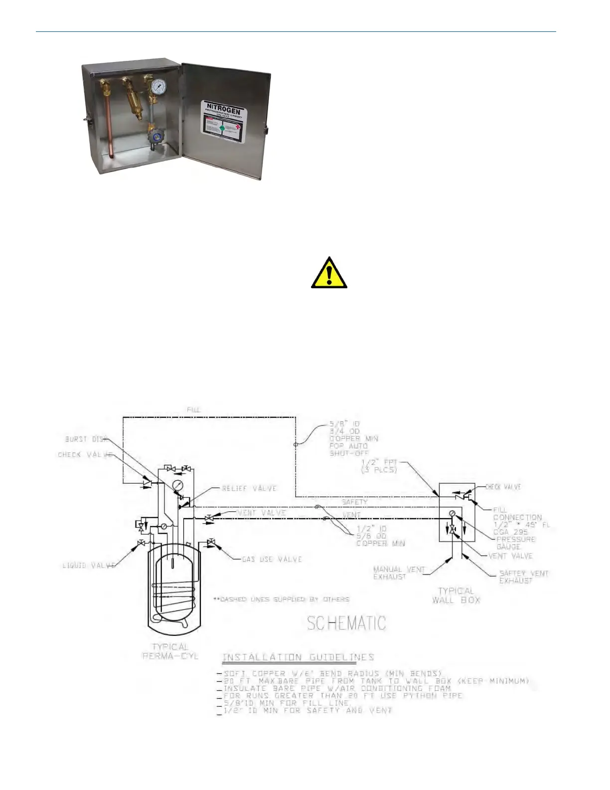
Photo 15 - Wall Box
Connections on the wall box are provided for the vent line,
liquid ll and relief line.
• Liquid Fill Line - The liquid ll should be piped using
a minimum diameter of 3/4” nominal copper. The
equivalent size stainless steel braided hose can also
be used. The line should be connected from the ll
connection in the wall box to the liquid ll check valve
on the Perma-Cyl System. When piping this line there are
a few guidelines that should be followed.
– Bends and elbows should be kept at a minimum.
When needed they should be made with a wide bend
radius. A minimum bend radius of 6” should be
observed.
– The length of the line from the tank to the box should
be kept to a minimum. Bare copper line can be used
for lines. If bare copper is used, it should be insulated
using air conditioning foam to keep condensation
from dripping off the piping.
– Line size should be a minimum 5/8” ID.
• Vent Line - The vent line should be run using 1/2”
nominal copper or the equivalent size stainless steel
braided hose. This line should connect the vent valve in
the wall box to the vent valve on the Perma-Cyl System.
• Relief Line - The relief line should be run using 1/2”
nominal copper. Kitec tubing or braided stainless steel
hose can also be used. Relief lines should be no smaller
in diameter than the outlet of the relief valve.
Caution! Restrictions in the relief valve
outlet piping should be avoided
to eliminate the possibility
of excessive back pressure
when the relief valve opens.
Restrictions could reduce the
required ow rate of the relief
valve and pose a potential safety
hazard.
Figure 5 - Installation Guideline Schematic