6
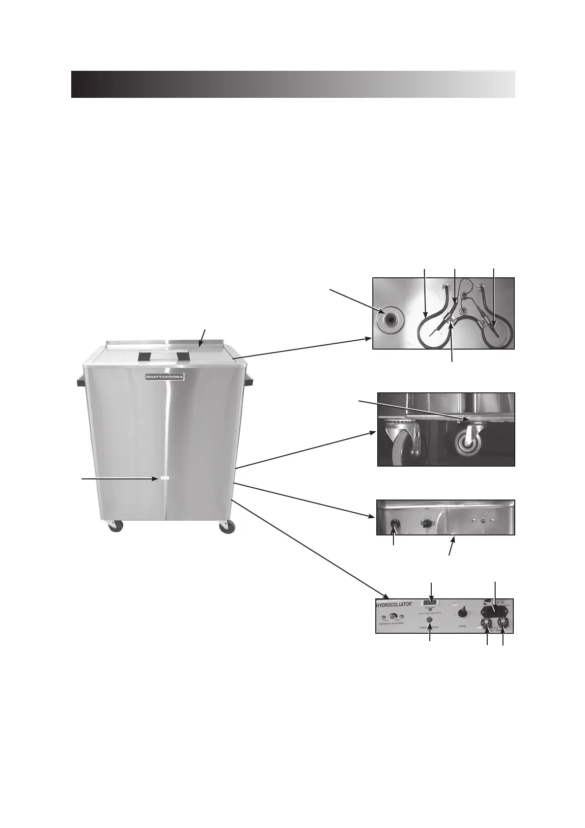
NOMENCLATURE
Diagram
1. Heating Element 9. Junction Box (J-Box) Cover
2. Drain 10. IEC connector
3. Overtemp Thermostat 11. Power Cord
4. Thermostat, Hydraulic 12. Drain Valve (Not Shown)
5. Bracket (Bracket & Bulb Thermostat A/B Assembly) 13. Reset Overtemp Button*
6. Lid 14. 6.3 Amp Fuses
7. 3-inch Caster 15. Pilot Lamp, Red
8. Overtemp Light 16. Pilot Lamp, Clear
NOTE: M-4 model shown; models will vary.
* All 220-240 Volt and M-4 120 Volt have this button
2
3
4
1
5
7
8
10
14
14
13
View Inside
6
Rear View Close-Up
(Lower Left Section)
16
Rear View 220/240 Volt
Rear View 120 Volt
9
11
Hydrocollator
®
Heating Units