7
OVERHAUL
The disassembly and reassembly procedures
can be accomplished by following the instructions
below and the drawings on pages 8 & 9. Use
extreme care during disassembly and
reassembly not to mar, nick or burr any
smooth surface that comes in contact with O-
rings. Before installing O-rings, be sure to apply
an O-ring lubricant. It is recommended that
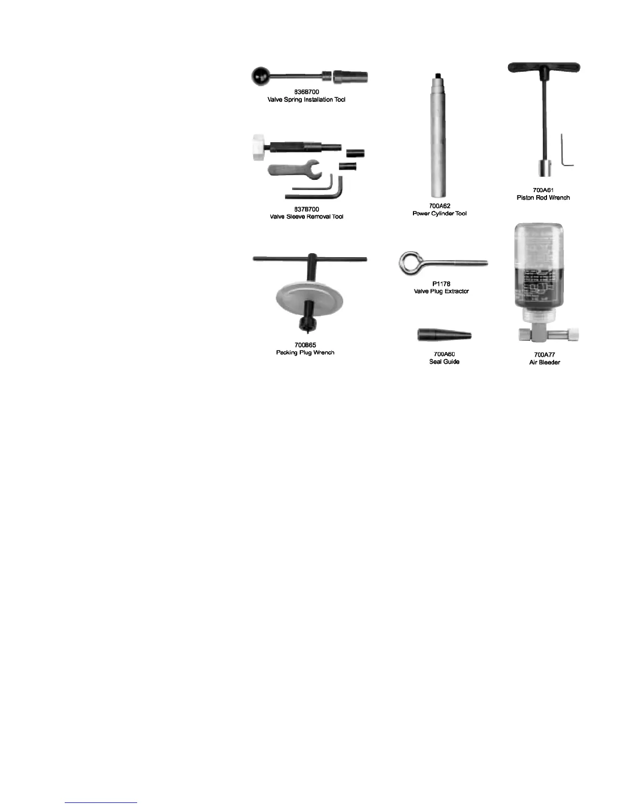
special assembly tools, which can be o r d e r e d
u n d e r p a r t n u m b e r G701/G704KT, be
used to overhaul this tool Service kit, G704KS,
which contains a complete set of O-rings, back-
up rings, screws, washers and gaskets should be
ordered.
Not shown, but included: 701A67 Seal Guide,
702B62 Power Cylinder Tool, 703A53 Seal
Guide, 702A64 Seal Guide, and 744-103 Seal
Guide.
AIR VALVE
Disconnect tool from air supply and remove retaining ring (46) and muffler (45). Insert a valve plug extractor (P1178) into end of
valve plug (44) and pull it out. Using the same procedures, pull out valve spool sub-assembly (52).
Use needle nose pliers to grasp the end of the spring (38), turn clockwise and pull out to dislodge from groove in handle.
With spring removed, valve sleeve (37) can be pulled out using the valve sleeve removal tool (837B700).
To reassemble, reverse the above procedures, being certain that all O-rings are properly lubricated. To avoid damaging the O-rings
(36), carefully install sleeve (37) with your finger. Gently push and wiggle sleeve to allow O-rings to slip past inner ports. Spring
(38) is best installed using a valve spring installation tool (836B700) to push the large diameter coil into the groove. This requires care
as the tool will not operate if the spring is not anchored firmly.
HEAD SUB-ASSEMBLY
Disconnect tool from air supply and remove the complete pulling head from the tool before attempting to disassemble the head
assembly.
Remove the four socket head cap screws (49). Lift head assembly from the handle (30). Remove O-ring (47) and gasket (48).
Empty the oil into a container by pouring from the handle. Dispose of the oil according to environmental regulations.
Remove end cap (9). Push against threaded end of head piston (4) and slide it out of head cylinder (1). Be careful not to
damage threads or cause burrs on polished head piston rod surface.
O-rings (2) and back-up rings (3) can now be removed using a bent hook. O-ring (8) can be removed in the same manner.
Upon re-assembly, be sure to install O-rings and back-up rings carefully to avoid cutting them. Always lubricate all O-rings. Just
prior to placing the head sub-assembly on to the handle, see Fill and Bleed Instructions. Also make sure to place O-ring (47) and the
gasket (48) on the top of the handle, and that they are properly oriented.
THE G701/G704KT TOOL KIT