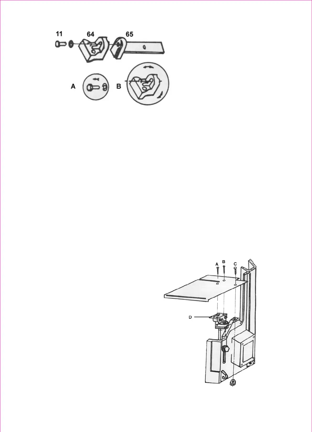
Figure (4)
Adjusting the blade
LUBRICATION
Lubricate the following components using lubricant, L-HV32
1.
Ball bearing -none.
2.
Blade guide bearing-none
3.
Driven wheel bearing-none.
4.
Vise lead screw- as needed.
5.
The driven gears run in the bath and will not require a lubricant change more than then once a
year. When needing a change, first put down the bead to a Horizontal position, then loosen 4
screw (#75) of the gear box open the cover (#93). Placing a pan under the tight lower corner of the
gear box, slowly raise the head until the oil flows out, Lower corner of the gear box, slowly raise
the head until the oil flows out, Lower head. Then wipe up excess oil and foreign matter with soft
rags. Then add lubricant into the box until it is full and not flow over. Close the cover, tighten 4
screws.
THE VERTIACAL CUTTING PLATE ASSEMBLY DRAWING.
Plate------
Vertical cutting plate stand
--------
6