2
These instructions are general in nature. It is assumed
that the installer is familiar with seals and certainly with
the requirements of their plant for the successful use of
mechanical seals. If in doubt, get assistance from someone
in the plant who is familiar with seals or delay the installation
until a seal representative is available. All necessary auxiliary
arrangements for successful operation (heating, cooling,
flushing) as well as safety devices must be employed. These
decisions are to be made by the user. The decision to use this
seal or any other Chesterton seal in a particular service is the
customer’s responsibility.
Transport and store seals in their original packaging.
Mechanical seals contain components that may be subject to
alteration and ageing. It is therefore important to observe the
following conditions for storage:
• Dust free environment
• Moderately ventilated at room temperature
• Avoid exposure to direct sunlight and heat
Do not touch the mechanical seal for any reason while it is
operating. Lockout or uncouple the driver prior to personal
contact with the seal. Do not touch the mechanical seal
while it is in contact with hot or cold fluids. Ensure that all the
mechanical seal materials are compatible with the process
fluid. This will prevent possible personal injury.
• For elastomers, storage conditions should conform to
ISO 2230; particularly storage temperatures between 15°C
(59°F) and 25°C (77°F). If stored outside these ranges, the
seal assembly or spare parts should be unboxed in a clean
environment, with ambient temperature within the previously
stated ranges, and allowed to recover for at least 1 hour
prior to installation. Failure to follow this step can impact the
performance of the seal.
1.0 CAUTIONS
2.0 TRANSPORT AND STORAGE
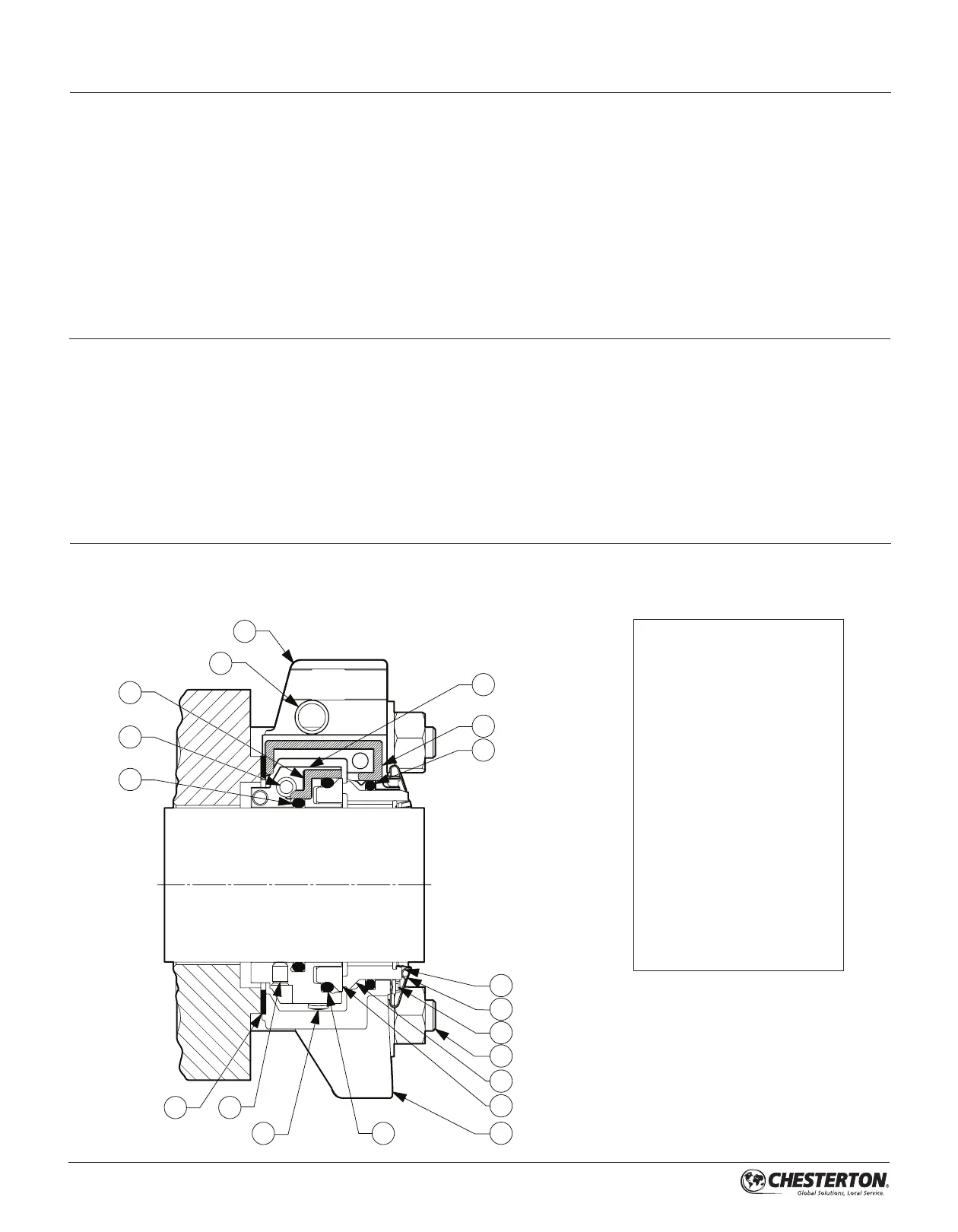
KEY
1 – Rotary Holder
2 – Holder Cap Screw (X)
3 – Holder Gasket
4 – Shaft O-Ring
5 – Rotary O-Ring
6 – Rotary Face
7 – Stationary Face
8 – Stationary O-Ring
9 – Gland Gasket
10 – Gland Cap Screw (Y)
11 – Stuffing Box Gasket
12 – Bolt Tab
13 – Spring
14 – Spring Retainer
15 – Centering Button
16 – Gland
17 – Stuffing Box Bolts (Z)
18 – Spring Lifter
19 – Holder Set Screw (W)
3.0 DESCRIPTION
3.1 Parts Identification
Figure 1
1
2
3
4
6
7
8
9
10
11
12
14
13
15
16
17
18
19
5