66
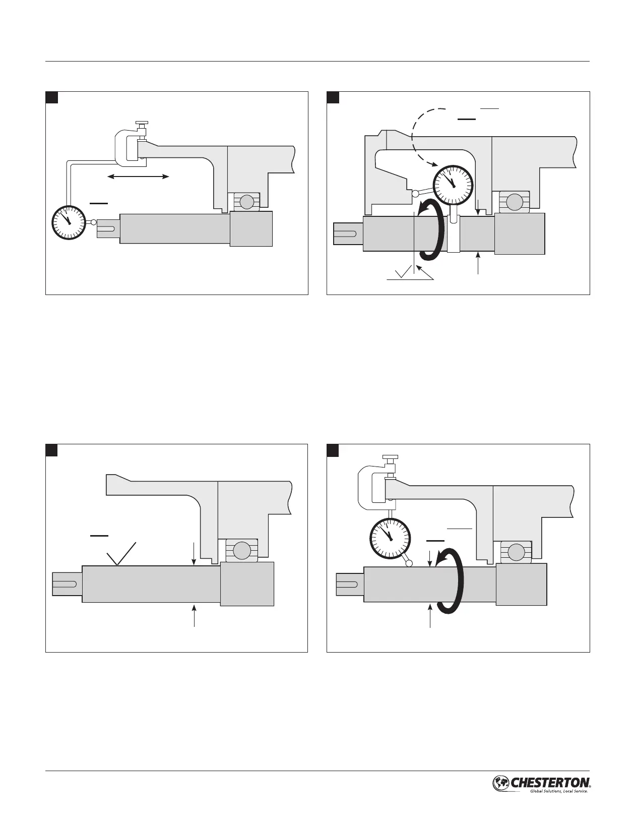
If practical, place the dial indicator tip on the end of the shaft
sleeve or on a step in the shaft to measure end play. Alternately
push and pull the shaft in the axial direction. If the bearings are
in good condition, end play should not exceed 0,13 mm (.005").
Remove all sharp corners, burrs, and scratches on the shaft,
especially in areas where the O-Ring will slide, and polish if
necessary to achieve a 0,8 micron (32 microinch) Ra finish.
Make sure the shaft or sleeve diameter is within 0,05 mm
(.002") of nominal.
Use a dial indicator to measure the shaft runout in the
area where the seal will be installed. Runout should not
exceed 0,001 mm TIR per millimeter (.001 inch TIR per inch)
of shaft diameter.
If possible, attach a base dial indicator to the shaft and rotate
both the indicator and shaft slowly while reading the runout
of the stuffing box face. Misalignment of the stuffing box face
relative to the shaft should not exceed 0,005 mm TIR per mm
(.005 in per inch) of shaft diameter.
The stuffing box face must be flat and smooth enough to
seal the gland. Surface roughness should be 3,2 microns
(125 microinch) Ra maximum for gaskets and 0,8 micron (32
microinch) Ra for O-Rings. Steps between halves of split case
pumps should be machined flat. Make sure the stuffing box is
clean and clear along it’s entire length.
4.0 PREPARATION FOR INSTALLATION
4.1 Equipment
2
1
3
4
.005"
0,13 mm
32 µ"
0,8 µm
R
a
ø
ø
200
<
<
ø
<
ø
1000
ø
<
.002"
0,05 mm
±
125 µ"
3,2 µm