- Avoid allowing any objects to enter inside the product or spilling any liquid into it.
- The product should not be used when:
1. The power supply cord or plug has been damaged
2. Objects have fallen or liquid has been spilled into the product
3. The product has been exposed to rain
4. The product does not appear to operate normally or exhibits a marked change in
performance
5. The product enclosure has been damaged.
- Do not attempt to service the product. Refer servicing to qualified personnel.
The symbol of crossed-out wheeled bin is intended to inform the user that the
product is the subject to the requirements of the WEEE Directive of the European Parliament.
i.e. after the end of its lifetime the product should not be disposed as unsorted municipal waste
but should be collected separately.
Introduction
This 2-channel professional power amplifier provides high-value performance.
Features
- independent clip-limiters and subsonic filters (40Hz)
- operating modes: stereo / mono / bridge
- balanced XLR inputs
- Speakon outputs
- LED indicators for BRIDGE, PROTECT, SIGNAL, LIMIT IN, LIMIT OUT, SIGNAL,
POWER
Front Panel
1. Power switch
2. Gain controls for CHANNEL A, CHANNEL B
LED indicators for respective channels
Blue ON indicators indicates that the amplifier is on, no matter if there is any input
signal.
Green SIGNAL indicators indicates the presence of the signal.
Yellow LIMIT IN and LIMIT OUT indicators indicates that limiter is activated and
reduces input or output signal.
Red PROTECT indicators indicates that the amplifier is overheated. In this case it is
recommended to reduce the gain or to switch off the amplifier until its temperature is
lower.
Yellow light of BRIDGE indicates that the amplifier works in BRIDGE mode.
4. Air inlet
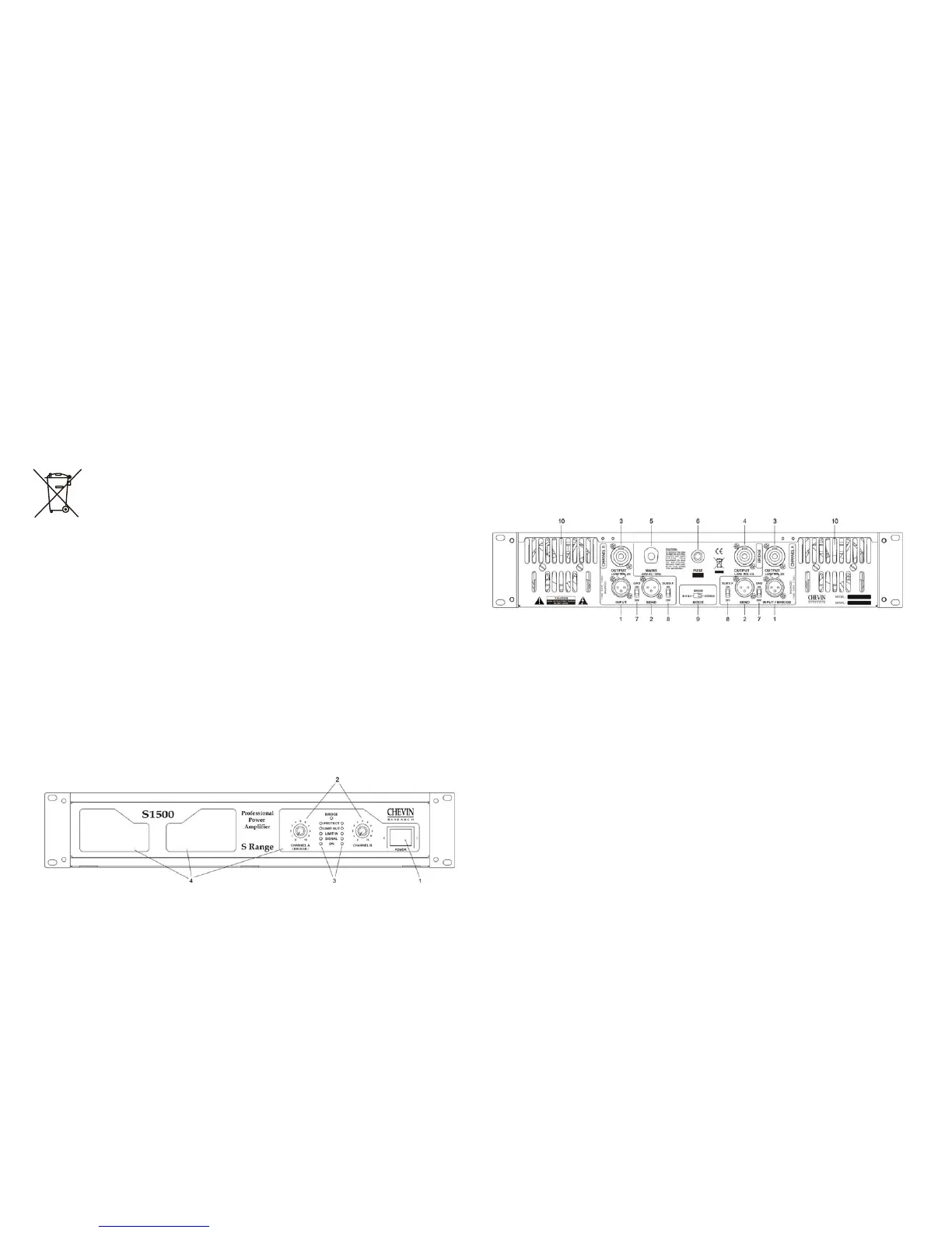
Rear Panel
1. INPUT connectors for CHANNEL A and CHANNEL B
2. SEND connectors providing the same signals as A and B input signals
3. OUTPUT connectors for CHANNEL A, CHANNEL B
4. OUTPUT BRIDGE – output connector for bridge mode
5. MAINS – AC power cable
6. MAINS FUSE or BREAKER
7. GND lift switches
8. Switches for subsonic filters of CHANNEL A and CHANNEL B
9. 3-position switch for MONO / STEREO / BRIDGE
10. Air outlet
Clip-Limiter
When audio signals drive the amplifier’s output circuit beyond its power capability it clips. The
clip limiter detects this and reduces the gain to minimise the amount of overdrive.
To preserve as much of the program dynamics as possible, the clip limiter works only if clipping
occurs frequently. Each channel has its own limiter that cannot be defeated.
3
4