EasyManua.ls Logo

Chicago Electric 98958 User Manual

Chicago Electric 98958
24 pages
To Next Page IconTo Next Page
Page #1 background imageLoading...
Page #1 background image
Visit our website at: http://www.harborfreight.com
Email our technical support at: productsupport@harborfreight.com
REV 15b
Owners Manual & Safety Instructions
Save This Manual Keep this manual for the safety warnings and precautions, assembly,
operating, inspection, maintenance and cleaning procedures. Write the product’s serial number in the
back of the manual near the assembly diagram (or month and year of purchase if product has no number).
Keep this manual and the receipt in a safe and dry place for future reference.
When unpacking, make sure that the product is intact
and undamaged. If any parts are missing or broken,
please call 1-888-866-5797 as soon as possible.
Copyright
©
2008 by Harbor Freight Tools
®
. All rights reserved.
No portion of this manual or any artwork contained herein may be reproduced in
any shape or form without the express written consent of Harbor Freight Tools.
Diagrams within this manual may not be drawn proportionally. Due to continuing
improvements, actual product may differ slightly from the product described herein.
Tools required for assembly and service may not be included.
Read this material before using this product.
Failure to do so can result in serious injury.
SAVE THIS MANUAL.
Question and Answer IconNeed help?

Do you have a question about the Chicago Electric 98958 and is the answer not in the manual?

Chicago Electric 98958 Specifications

General IconGeneral
Input Voltage120V
Welding ProcessesFlux Core
Amperage Output90A
Duty Cycle20% @ 90A
Wire Size0.030 in.
Output Current Range70-90A

Summary

IMPORTANT SAFETY INSTRUCTIONS

WARNING SYMBOLS AND DEFINITIONS

Explains hazard symbols and their meanings.

Work Area Safety

Guidelines for maintaining a safe work environment.

Personal Safety

Personal Protective Equipment

Lists essential safety gear, including clothing and eye protection.

Operational Awareness and Hazards

Emphasizes alertness, common sense, and warns about inhalation hazards.

California Proposition 65 Warnings

Notifies about chemicals known to cause cancer and reproductive harm.

Equipment Setup and Operation Safety

Setup Safety Precautions

Ensures safe preparation, gas settings, and cylinder handling.

Pre-Use Inspection and Operation Safety

Procedures for inspecting equipment and general operational safety.

Service, Maintenance, and Symbology

Service and Parts Guidelines

Stresses qualified service and using identical replacement parts.

Understanding Safety Symbology

Explains various symbols and their meanings related to safety and operation.

Specifications and Initial Setup

Technical Specifications

Details nozzle sizes, material thickness, regulator types, and hose specifications.

Work Area Preparation and Assembly

Steps to prepare a safe work area and begin tool assembly.

Tool Assembly - Connections

Torch Handle and Attachment Setup

Connecting the torch handle, cutting attachment, and welding nozzle.

Leak Test Preparation

Instructions on performing leak tests after connecting components.

Leak Testing Procedures

Soapy Water Leak Detection

Detailed steps for performing a soapy water leak test on connections.

Gauge Monitoring for Leaks

Procedure for monitoring regulator gauges to detect minor leaks.

Leak Analysis and System Confirmation

Diagnosing Leak Locations

Interpreting gauge readings to identify leak locations.

Verifying System Integrity

Steps to confirm system integrity after leak testing.

Welding - Tip Settings and Data

Welding Tip Pressure Settings

Guidance on setting pressures based on metal thickness and nozzle size.

Welding - Setup and Ignition Prep

Pre-Operation Setup and Checks

Instructions for setting up, closing valves, and adjusting regulators.

Preparing for Ignition

Proper grip and positioning for holding the torch and striker.

Welding - Flame Adjustment

Lighting and Adjusting Acetylene Flame

Steps for safely igniting and adjusting the acetylene flame.

Achieving a Neutral Flame

Detailed guide on adjusting the flame for optimal welding.

Welding Shutdown Procedure

Safely Closing Valves and Regulators

Step-by-step guide to safely shut down the welding equipment.

Cutting - Tip Settings and Data

Cutting Tip Pressure Settings

Guidance on setting pressures based on metal thickness and tip size.

Cutting Tip Flow Data

Table specifying cutting tip sizes, material thickness, and pressure settings.

Cutting - Setup and Ignition Prep

Pre-Operation Setup and Checks

Instructions for setting up, closing valves, and adjusting regulators for cutting.

Preparing for Ignition

Proper grip and positioning for holding the torch and striker.

Cutting - Flame Adjustment

Lighting and Adjusting Acetylene Flame

Steps for safely igniting and adjusting the acetylene flame for cutting.

Pre-heat Flame Adjustment

Detailed guide on adjusting the pre-heat flame for optimal cutting.

Cutting Shutdown Procedure

Safely Closing Valves and Regulators

Step-by-step guide to safely shut down the cutting equipment.

Maintenance and Troubleshooting

General Maintenance Guidelines

Safety warnings and general procedures for maintaining the torch kit.

Troubleshooting Common Issues

Diagnosing and resolving problems like gas odor or irregular flames.

Parts Information

Accessory Parts List

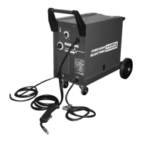
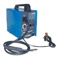
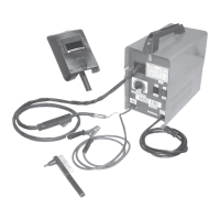
Lists common accessories included with the welding kit.

Important Repair Disclaimer

Warns about self-repair risks and recommends professional service.

Oxygen Regulator Parts Diagram

Oxygen Regulator Component Breakdown

Detailed breakdown of parts for the oxygen regulator with diagrams.

Torch Handle Parts Diagram

Torch Handle Component Breakdown

Detailed breakdown of parts for the torch handle with diagrams.

Cutting Attachment Parts Diagram

Cutting Attachment Component Breakdown

Detailed breakdown of parts for the cutting attachment with diagrams.

Acetylene Regulator Parts Diagram

Acetylene Regulator Component Breakdown

Detailed breakdown of parts for the acetylene regulator with diagrams.

Limited 90 Day Warranty

Warranty Terms and Conditions

Outlines the terms, limitations, and duration of the product warranty.

Related product manuals