- 13 -
Bodywork
The alternator, the engine, the cooling system, etc. are
enclosed in a sound-insulated bodywork that can be
opened by means of side doors (and service plates).
The recess in the roof has a lifting rod in the middle.
To be able to lift the generator by means of a forklift,
rectangular holes are provided in the frame.
The earthing rod, connected to the generator’s earth
terminal is located at the side of the frame.
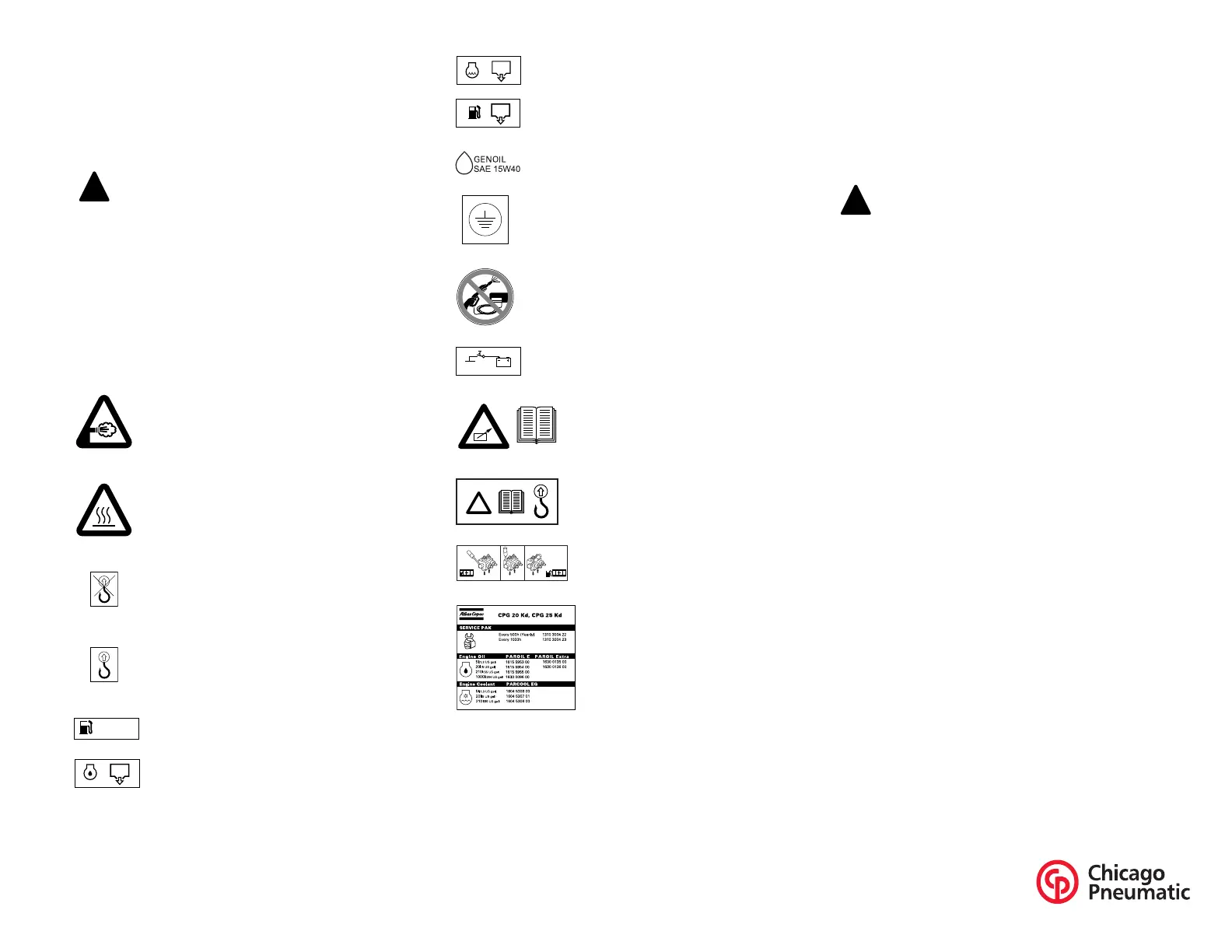
Markings
A brief description of all markings provided on the
generator is given hereafter.
Drain plugs and filler caps
The drain holes for the engine oil, the coolant and the plug
for the fuel, are located and labelled on the frame; the fuel
drain plug at the front, the others at the service side.
The drain flexible for engine oil can be brought to the
outside of the generator through the drain hole.
The filler cap for the engine coolant is accessible via an
opening in the roof. The fuel filler cap is located in the side
panel.
Never use the guiding rods to lift the
generator.
Indicates that the engine exhaust is a hot and
harmful gas, which is toxic in case of
inhalation. Always make sure that the unit is
operated outside or in a well-ventilated
room.
Indicates that these parts can become very
hot during operation (e.g. engine, cooler,
etc.). Always make sure that these parts are
cooled down before touching them.
Indicates that the guiding rods may not be
used to lift the generator. Always use the
lifting rod in the roof of the generator to lift
it.
Indicates a lifting point of the generator.
Indicates that the generator may be refuelled
with diesel fuel only.
Indicates the drain for the engine oil.
Indicates the drain for the coolant.
Indicates the drain plug for the engine fuel.
Use GENOIL 15W40 only.
Indicates the different earthing connections
on the generator.
Indicates that the alternator should not be
cleaned with high pressurised water.
Indicates the battery switch.
Indicates that the unit may start
automatically and that the
instruction book has to be
consulted prior to use.
Read the instruction manual
before using the lifting eye.
Indicates the 3-way valve.
Indicates the partnumbers of the
different service packs and of
the engine oil. These parts can
be ordered to the factory.
Position 1 Closed Position 2
The drain hole can also be used to guide
external fuel tank connections. When
connecting an external fuel tank, use the 3-
way valves. Refer to External fuel tank
connection (with/without quick couplings).
 Loading...