Instruction 2111.80B 04/05 7
Discharge Piping
A suitable check valve and gate valve should be installed in the discharge pipe near the pump to protect the
pump from reverse flow and excessive back-pressure. The check valve should be placed between the pump
and the gate valve. If increasers are used to accommodate larger discharge piping, they should be placed
between the check valve and the pump. The selection of discharge pipe size should be made with due reference
to friction loss and should never be smaller than the pump discharge size.
At the end of a "pump down cycle" some air may enter the pump and remain trapped by the discharge check
valve. To facilitate the expulsion of this trapped air, an automatic air release valve and open vent pipe should be
installed from the pump backplate to the wet well.
Alignment must always be rechecked after piping connections have been made.
B. WOOD'S SURE-FLEX
®
COUPLINGS
The couplings include elastomeric sleeves to compensate for temperature changes during operation. They are
NOT to be used to compensate for misalignment of the motor and pump shafts. The following procedures apply
to Wood's Sure-Flex® couplings only. When couplings other than these are supplied, please refer to the
specific manufacturer's instructions. If questions arise as to the type of coupling supplied with the unit, contact
your CHICAGO PUMP representative.
Position the flanges on the shaft to approximately achieve the "Y" dimension (dimension across coupling
flanges, outside to outside) shown in Table 1. It is usually best to have an equal length of shaft extending into
each flange. Move one flange to its final position and tighten the set screws. Slide the other flange far enough away
to install the sleeve. With a two-piece sleeve, do not move the wire ring to its final position; allow it to hang loosely
in the groove adjacent to the teeth.
Slide the loose flange on the shaft until the sleeve is completely seated in the teeth of each flange. (The "Y"
dimension is for reference and not critical.) Secure the flange to the shaft. Different coupling sleeves require
different degrees of alignment precision. Locate the alignment values for your sleeve and type in the table.
Check parallel alignment by placing a straightedge across the two coupling flanges and measuring the
maximum offset at various points around the periphery of the coupling without rotating the coupling. If the
maximum offset exceeds the figure shown under "Parallel" in the table, realign the shafts by placing shims
underneath the motor.
Check angular alignment with a micrometer or caliper. Measure from the outside of one flange to the outside of
the other at intervals around the periphery of the coupling. Determine the maximum and minimum dimensions
without rotating the coupling. The difference between the maximum and minimum must not exceed the figure
shown under "Angular" in the table. If a correction is necessary, be sure to recheck the parallel alignment.
If the coupling employs the two-piece sleeve with the wire ring, force the ring into its groove in the center of the
sleeve. It may be necessary to pry the ring into position with a blunt screwdriver.
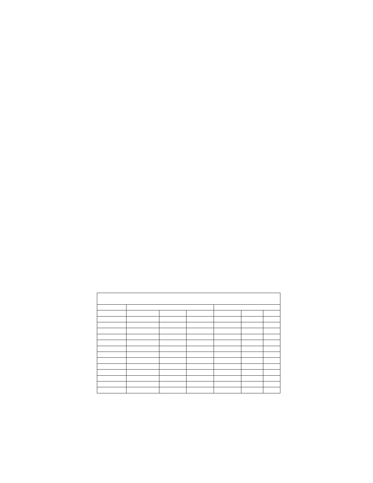
TABLE 1
MAXIMUM RPM AND ALLOWABLE MISALIGNMENT
(Dimensions in Inches)
Types JE, JN, JES. JNS, E & N *Type H & HS
Sleeve Size Parallel Angular Y Parallel Angular Y
3 .010 .035 1.188 ... ... ...
4 .010 .043 1.500 ... ... ...
5 .015 .056 1.938 ... ... ...
6 .015 .070 2.438(1) .010 .016 2.500
7 .020 .081 2.563 .012 .020 2.625
8 .020 .094 2.938 .015 .025 3.000
9 .025 .109 3.500 .017 .028 3.563
10 .025 .128 4.063 .020 .032 4.125
11 .032 .151 4.875 .022 .037 4.938
12 .032 .175 5.688 .025 .042 5.750
13 .040 .195 6.688 .030 .050 6.688
14 .045 .242 7.750 .035 .060 7.813
16 .062 .330 10.250 ... ... ...
*Type H and HS sleeves should not be used as direct replacements for EPDM or Neoprene sleeve.
(1) Value when using 6J flanges is 2.125