Do you have a question about the Chicago Welding 94164 and is the answer not in the manual?
Keep your work area clean, well lit, and free of clutter.
Ensure proper grounding, avoid wet conditions, and protect power cords.
Stay alert, dress properly, and avoid accidental starting.
Use the correct tool for the job and maintain tools for safe operation.
Tool service must be performed by certified and licensed technicians only.
When servicing a tool, use only identical replacement parts to ensure safety.
Requires a 220 VAC, 3-prong, grounded power cord plug installed by an electrician.
Maintain labels and nameplates on the Welder for important information.
Ensure the Power Switch is OFF before plugging in or making adjustments.
Use the Welder for its intended purpose and do not force it.
Keep the work area well lit and free of obstructions, grease, oil, and debris.
Wear ANSI-approved safety clothing and devices, including eye protection and flame-resistant gear.
Remove combustible materials, use fire-resistant screens, and check for fire evidence.
Ensure adequate ventilation or use a respirator to avoid inhaling toxic fumes and gases.
Welding produces toxic fumes and gases that can cause serious health issues.
Do not touch live electrical parts; wear dry, insulating gloves.
Cylinders can explode if damaged; handle with care and keep away from electrical circuits.
Consult a physician before use if you have a pacemaker due to electromagnetic fields.
The manual cannot cover all situations; common sense and caution are the operator's responsibility.
Product produces chemicals known to cause cancer and birth defects.
Requires a 220 VAC, 3-prong, polarized, twistlock plug installed by an electrician.
Connect to a properly grounded outlet using a three-wire cord and plug.
An extension cord must never be used with this item to prevent damage or fire.
Key symbols used in the manual for safety and operation.
Verify that all listed parts are included and contact customer service if any are missing.
Insert the handle into the handle sockets and attach to the side panel.
Assemble the handle onto the face shield by lining up tabs and pressing.
Open the access panel and install a wire spool onto the axle.
Secure the wire end and guide it through the wire feed leader and torch cable.
Turn off the welder before changing wire rollers, contact tips, or settings.
Configure electrode polarity for gasless flux core or solid-core wire.
Securely attach a gas cylinder and regulator/flow meter for shielding gas.
Practice on scrap metal to develop skill before starting projects.
Understand the welder's duty cycle to prevent overheating and premature failure.
Adjust voltage controls, connect gas hose (if applicable), and clamp the ground.
Maintain correct torch angle and stickout for proper weld bead formation.
Consult the chart for recommended voltage and wire speed settings based on material.
Lift the welding wire away, turn off the welder, and unplug the unit.
Addresses issues like burn-through, drooping, or insufficient penetration.
Covers gaps between beads or workpieces due to technique or material.
Diagnoses small cavities in the bead and crooked or wavy bead formation.
Identifies and provides solutions for grainy, large spatter.
A method to test weld quality by deforming a test weld.
Inspect and clean the nozzle for optimal weld quality.
Check and clean the contact tip for proper wire feeding and arc stability.
Procedure for replacing the internal liner of the welding torch.
Diagram illustrating the electrical connections of the welder's components.
A comprehensive list of all parts with descriptions and quantities.
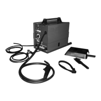
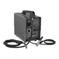
Visual guide showing how the welder's parts are assembled together.
Solutions for when the wire feed motor runs but wire doesn't feed.
Troubleshooting steps for tangled wire during operation.
Addresses issues causing an unstable or inconsistent welding arc.
Steps to resolve issues when the welder fails to turn on.
Diagnoses and resolves problems causing a weak welding arc.
Troubleshooting for when the wire feeds but the welding arc fails to ignite.
Addresses problems related to shielding gas not flowing correctly.
Details the warranty period, coverage, and procedure for making a claim.
| Brand | Chicago Welding |
|---|---|
| Model | 94164 |
| Category | Welding System |
| Language | English |