For technical questions, please call 1-800-444-3353;
Troubleshooting section at end of manual.
Page 20SKU 94164
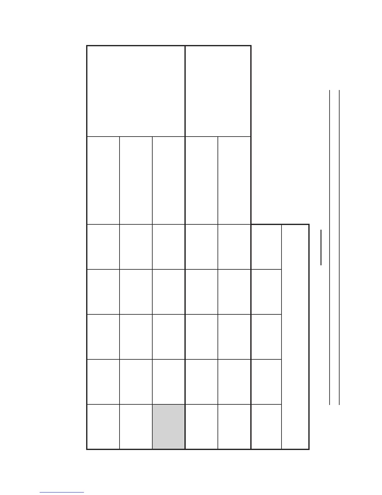
WELD SETTINGS CHART
FIGURE N
Welding Instructions continued on next page.
Top gures are Voltage Settings.
Bottom number is Wire Speed Setting.
NOTE: The numbers within the spaces are the
approximate wire feed/voltage settings recom-
mended* for this wire size and material thickness.
Material Thickness (Steel)
.035”-.047” .047”-.075” .075”-.125” .125”-.157”
.157”-.250”
Wire Size
(Flux Core, Mild Steel)
.023”
MIN 1
1
MIN 2
3
MAX 1
4
MAX 1
6
MAX 2
6
.030”
MIN 1
1
MIN 2
2
MAX 1
3
MAX 1
5
MAX 2
5
Wire Size
(Solid Core, Mild Steel)
.023”
MIN 2
4
MAX 1
7
MAX 2
5
MAX 2
8
.030”
MIN 2
2
MAX 1
5
MAX 1
6
MAX 2
5
MAX 2
7
.035”
MIN 2
1
MAX 1
2
MAX 1
3
MAX 2
4
MAX 2
5
*This chart is only intended to show general guidelines for different wire sizes and for different
thicknesses of material. The settings should only be used at the beginning of a weld and must be
adjusted after stopping and carefully inspecting the weld. Proper welding takes good technique
and practice.