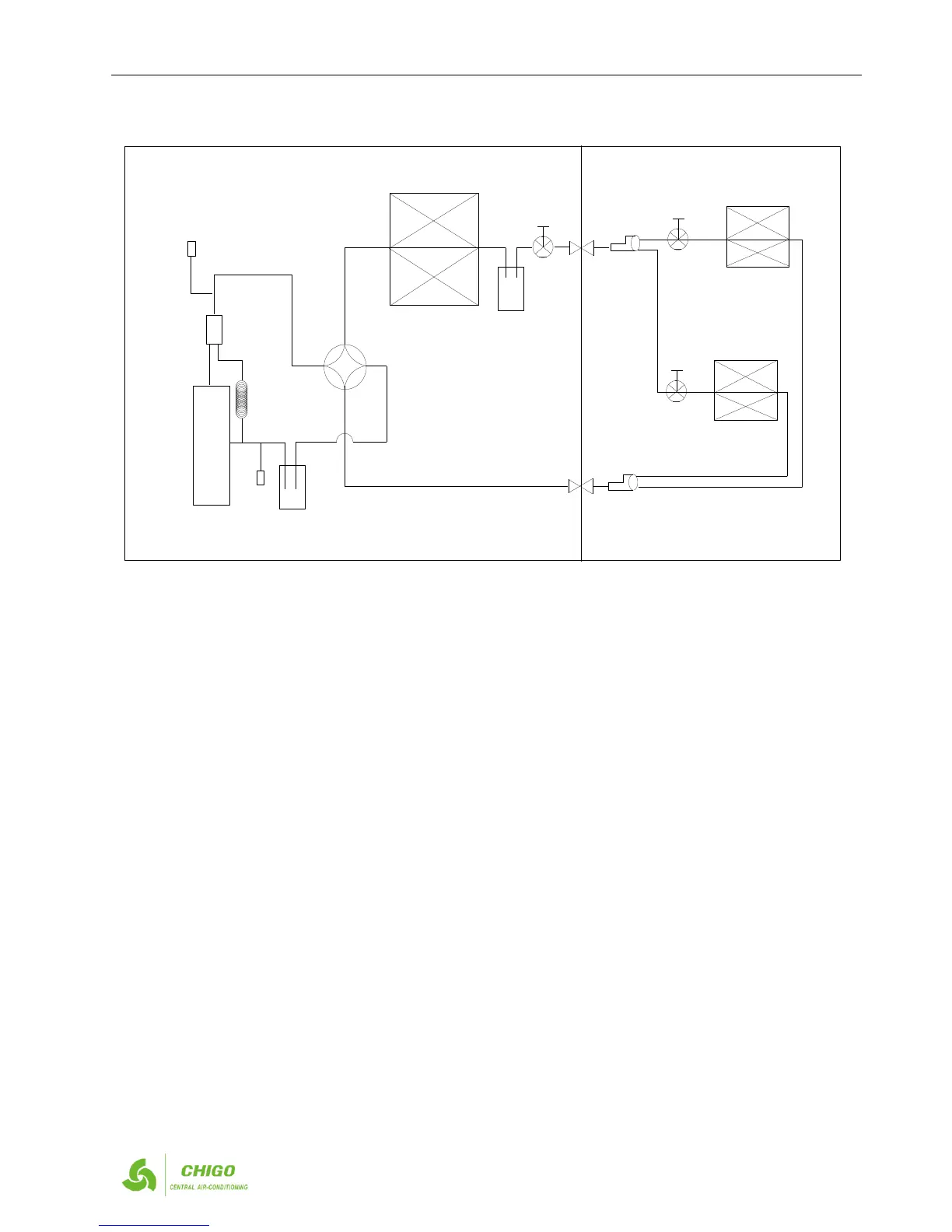
3. Outdoor refrigerant circuit diagram
3.1 10KW,12.5KW,14KW,16KW
Remarks:
Discharge temperature sensor, totally there’re 3 pieces, besides the top sensor of 2 fixed speed compressor.
There’re Pipe temperature sensor
3.2 Key parts
3.3.1 Oil Separator
It is used to separate oil from high pressure & temperature gas refrigerant that is pumped out from compressor. The separation
efficiency is up to 99%, it makes the oil return back to each compressor very soon.
3.3.2 Liquid accumulator
It is used to store the overmuch liquid refrigerant, and guarantee the refrigerant from the outdoor to indoor unit is in liquid status.
3.3.3 Gas-liquid separator
It is used to store the liquid refrigerant and oil, it can protect the compressor from liquid hammer.
3.3.4 Four-way valve (ST)
Closes in cooling mode and opens in heating mode
3.3.5 EXV (Electromagnetic expansion valve)
a) Max. Open degree is 480 pulses.
b) Generally when system is electrified the EXV closes 700pulse first, then opens to 350 pulse and stand by. Then the unit is started,
it opens to the right pulse.
c) When the running outdoor unit receives OFF signal, the EXV of auxiliary unit will stop while main unit is running and auxiliary
unit is stopped at the same time. If all outdoor units are stopped, the EXV will close first, and then open to the pulse of stand-by.
d) 8HP/10HP/12HP unit has one EXV, 14/16HP unit has two EXVs.
3.3.6 Hi pressure switch
To protect the system when system high pressure up to 4.4MPa.
3.3.7 Low pressure switch
To protect the system when system low pressure low to 0.14MPa.
3.4 Key functions
 Loading...