Chiltrix Inc. www.chiltrix.com
G valves Continued
A booster pump may be installed in front of the G2 valve when installing the DHW option if the head,
including pressure drop of the DHW tank coil, exceeds the head allowed by the pump curve when
calculated at 7GPM. If a booster pump is needed for a different reason, this location should also be used.
Check the DHW tank pressure drop from the Chiltrix Tank Manual or tank provider coil specs if not using a
Chiltrix tank. The G2 valve should be located as close to the cx50 as practical.
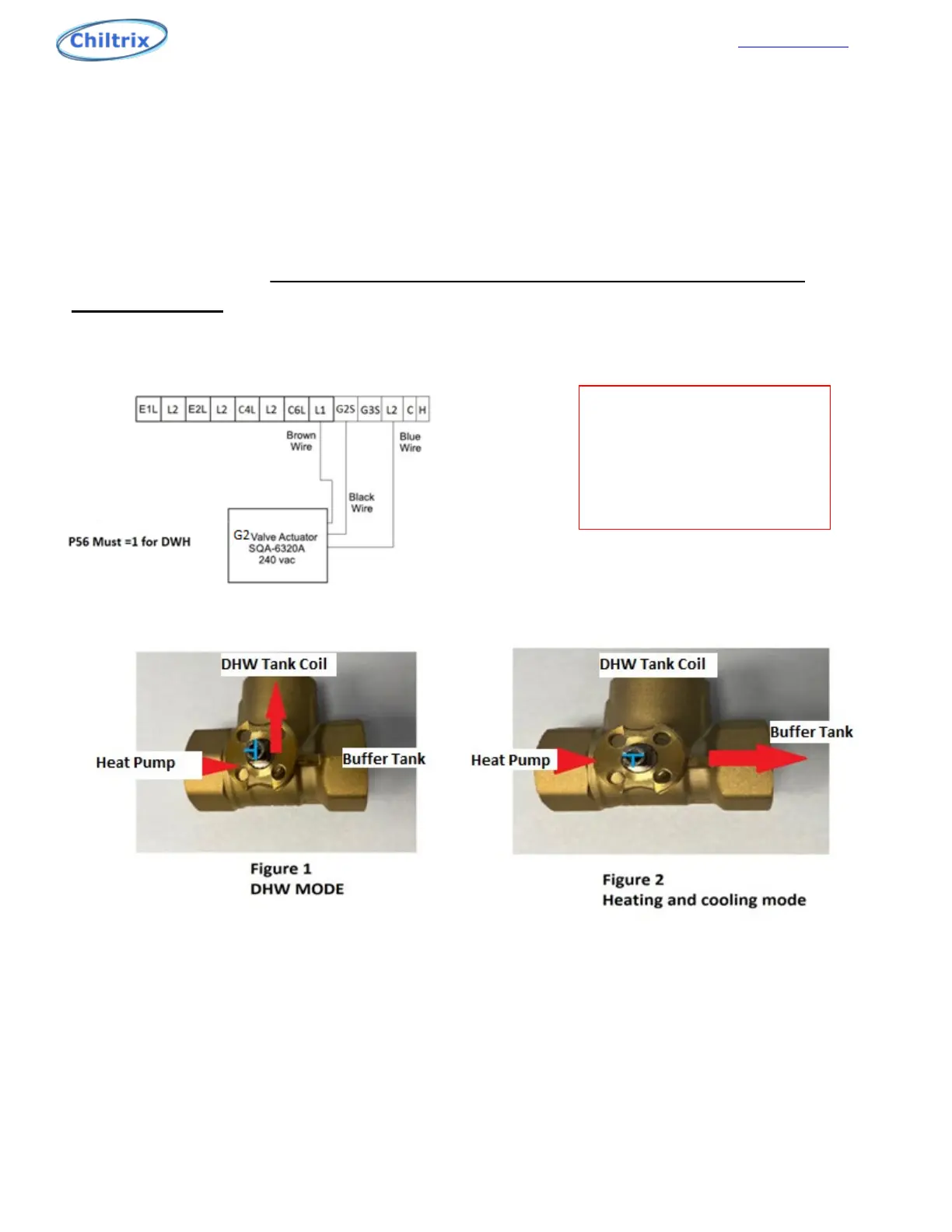
G2 Valve Wiring Note; The G2 control wire is connected to G2 on the
terminal strip
G2 and G3 valves use 220v Primary from the cx50. Use conduit and install per local
code.
Figure 1, this is the direction of flow when it is activated for DHW. Figure 2, this is the direction of flow
when it is activated for Heating or Cooling. When the brown wire is connected to L1, the blue wire
connected to L2, and the black control wire is connected to G2S the valve is controlled by voltage at L2 and
G2S. Voltage at G2S activates the valve for DHW. No voltage at G2S activates the valve for Heating/Cooling.
See wiring diagram above. Note: Use the center “T” screw as a visual cue for valve position. When
installing the g1 valve, manually turn the position of the valve, if needed, to match figure 1 and then
install the orange actuator while ALL power to the unit is off. NOTICE THE BLUE T IN THE DIAGRAM, the
T corresponds to a T cut into the stem of the valve.
23
If one or more V18b units
are used they must be in
front of the G2 Valve
(upstream from G2)
See V18b manual.