Do you have a question about the Chiltrix CX50 and is the answer not in the manual?
Covers essential safety rules for operation and installation.
Proper methods for moving and storing the heat pump unit.
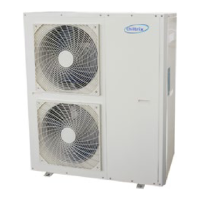
Identifies key parts of the CX50 unit with a diagram.
Provides physical measurements of the heat pump.
Recommends piping configurations and buffer tank usage.
Guidance on selecting pipe sizes and managing water flow.
Advises on installing filters and strainers for system protection.
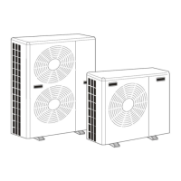
Illustrates recommended piping for multiple stacked units.
Shows both preferred and non-preferred parallel piping methods.
Details a system design for multiple fan coil units.
Specifies insulation standards for all piping.
Explains buffer tank roles in radiant systems and sizing.
Important notes regarding backup heat within buffer tanks.
Demonstrates calculating head loss caused by pipe fittings.
Details calculations for pipe friction and fan coil head requirements.
Discusses expansion tank needs and air separator installation.
Covers wye strainer cleaning and PEX fitting friction loss.
Displays the performance curve for the Grundfos UPMXL pump.
States the inherent head provided by the CX50 unit itself.
Advises on using propylene glycol for freeze protection.
Details how glycol percentage affects required flow rates.
Warns against using PVC with glycol due to ESC risks.
Specifies recommended installation positions and mounting pads.
Details necessary clearances for service, ventilation, and obstacles.
Step-by-step guide to install the internal circulation pump.
Crucial advice to avoid damaging piping during installation.
Shows how to distinguish positive and negative pump control wires.
Illustrates the connections for pump power and control wiring.
Details the proper connection of the pump ground wire.
Emphasizes qualified installation and adherence to NEC standards.
Specifies power supply requirements and surge suppression advice.
Shows the layout of the main electrical terminal block.
Locates key components and connectors on the main control board.
Details wiring for C4 Pump and V18 SSR connections.
Provides a comprehensive wiring diagram with wire color codes.
Explains how to connect a second pump and use a relay.
Details G2 valve function in DHW mode and its wiring.
How to set the target temperature for domestic hot water.
References the Tank Manual and provides sensor handling instructions.
Shows a setup for two chillers providing DHW.
Guidance on optimal placement of G2 valve and DHW tank.
Discusses booster pump use and G2 valve wiring details.
Illustrates G2 valve operation in DHW and heating/cooling modes.
Details G3 valve wiring and its control via parameter P50.
Explains the G3 valve's role in seasonal switching and solar preheat.
Shows the G3 valve in a system diagram for heating and cooling.
Clearly labels the ports on the G3 valve body.
Details the setup for a secondary heat source, excluding V18.
Lists parameters required for activating the secondary heat source (E2).
Explains using external relays for mode selection, not heating/cooling calls.
Provides important notes and terminal strip connections for relay control.
Illustrates wiring relays for standby, cooling, and heating modes.
Notes that relay control overrides other inputs and disables timers.
Lists the necessary parts for a system flush/fill valve assembly.
Detailed instructions for filling the system with glycol and water.
Procedures for removing air bubbles and monitoring system pressure.
Methods for purging air from DHW tanks and fan coils.
Steps to properly balance flow through each fan coil unit.
Overview of the controller's functions, modes, and display.
Explains the meaning of various icons used on the controller.
Guides on navigating to the parameter checking screen.
Shows an example of how parameters are displayed on the desktop.
Explains how to enter the system settings and administrator menus.
Lists available settings like language, time, and backlight.
Interface for choosing the display language.
Setting the duration before the screen saver activates.
Steps for calibrating the touchscreen for accurate input.
Interface for setting the system's date and time.
How to adjust the display's backlight intensity.
Overview of the timer feature for scheduling operations.
Details on setting ON/OFF times and modes for timers 1 and 2.
Details on setting ON/OFF times and modes for timers 3 and 4.
How to choose the operational mode (e.g., Heating, DHW) for timers.
Example of how to set a timer to be off or on specific days.
Instructions to access administrator functions using a password.
Shows an example of P parameter settings and their values.
Lists and explains the available operating modes for the unit.
Details the function for automatically adjusting heating curves.
How to access the error log and manage recorded errors.
Examples of error messages that may appear in the log.
Shows where to find interface, firmware, and software versions.
Guides on accessing C-Parameters, P-Parameters, and Error Codes.
Lists and explains parameters from P00 through P39.
Lists and explains parameters from P40 through P63.
Lists and explains parameters from P64 through P82.
Lists and explains parameters from P83 through P112.
Lists and explains C parameters related to temperatures and statuses.
Lists and explains C parameters related to fan speeds, pumps, and modes.
Lists common error codes related to sensor and protection faults.
Lists error codes related to electrical faults and communication issues.
Discusses the advantages and common misunderstandings of outdoor reset.
Explains why lower operating temperatures improve heat pump efficiency.
Recommends using reset for energy savings by adapting to weather.
Guides on setting P48 and P49 for dynamic outdoor reset.
Instructions for enabling and configuring the "AU TEMP" mode.
Explains the cx50's ability to switch modes automatically based on outdoor temperature.
Details suggested settings, compatibility, and activation steps.
Essential checks to perform before initiating the commissioning process.
Guidance on filling the system with glycol and performing initial tests.
Important notes regarding initial operation mode and antifreeze function.
Identifies the specific internal pump model used in the CX50.
Presents the performance curve for the Wilo Yonos pump.
| Model | CX50 |
|---|---|
| Category | Heat Pump |
| Refrigerant Type | R410A |
| Compressor Type | Scroll |
| Refrigerant | R410A |
| Seasonal Energy Efficiency Ratio (SEER) | 20 |
| Coefficient of Performance (COP) | 4.2 |
| Power Supply | 230V/1Ph/60Hz |
| Heating Capacity (at A7/W35) | 20, 470 BTU/h |
| Cooling Capacity (at A35/W18) | 17, 060 BTU/h |
| COP (Heating) (at A7/W35) | 4.2 |
| Dimensions (HxWxD) | 93 x 46 x 78 in |