Do you have a question about the CHINT NF2 Series and is the answer not in the manual?
NF2 series load switch: main use, rated voltage, current, function, standards compliance.
NF2 load switch type designation and its meaning breakdown, including model, poles, and accessories.
Normal operating, installation, transport, and storage conditions for NF2 load switches.
Key electrical and mechanical specifications for NF2 load switch models.
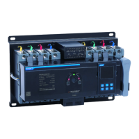
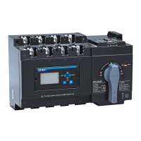
Technical data for the NF2-HH mechanical combination system.
Outline and installation dimensions for various NF2 load switch models and mounting types.
Pre-installation checks including nameplate, appearance, and operating performance verification.
Instructions and precautions for screw, guide rail, and panel installation methods.
Procedure for installing auxiliary contacts and additional poles on the load switch.
Measures for removing dust, water vapor, and corrosive substances.
Checking wiring terminals, moving parts, and fasteners for reliability.
Recommendation for monthly checks and maintenance of the load switch.
Proper procedures for disconnecting, storing, and protecting the product.
24-month warranty terms and conditions, excluding user-caused damage.
Guidelines for proper disposal of scrapped products and components.
Required details for placing an order: model, quantity, delivery time, and consignee.
Examples illustrating how to order products including main body, additional poles, and accessories.
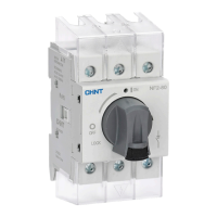
The NF2 series load switch is a versatile electrical component designed for various applications in AC circuits. It serves primarily as a means to isolate faulty equipment or perform power outage maintenance, ensuring safety and operational efficiency. Beyond isolation, it can function as the main switch for machine tools, fans, and pumps, and even as a start-stop switch for small-capacity motors. The design adheres to international standards, including IEC/EN 60947-3 and GB/T 14048.3, ensuring reliability and compliance.
The NF2 load switch is engineered for robust performance in electrical systems. Its core function is to provide a reliable means of making and breaking electrical circuits, particularly for isolation purposes. The switch is built with a contact system that employs a double-breakpoint bridge structure, enhancing its breaking capacity and reliability. The operating mechanism utilizes spring energy storage, which ensures that the connection and breaking speeds are independent of the operator's handle speed. This design guarantees consistent and effective circuit interruption, regardless of how quickly the handle is moved.
The switch's modular design allows for various configurations and enhancements. A standard 3-pole body can be combined with additional accessories to create a 6/8-pole load switch or a 3/4-pole transfer switch. Furthermore, the addition of a neutral pole, grounding pole, or auxiliary contacts expands its functional versatility, allowing it to meet diverse system requirements. The wiring method employs a wire frame design, facilitating secure and efficient electrical connections.
The NF2 load switch is designed for ease of installation and operation across a range of environmental conditions.
Installation: The switch offers multiple installation methods to suit different applications:
The installation process is straightforward. For screw installation, the switch is first confirmed to be in the "off" state. A hole is opened on the mounting plate, and the switch is connected and tightened with screws. For guide rail installation, the guide rail is fixed in the cabinet, and the switch is then installed onto the rail. Panel installation involves assembling the body, installation panel, and installation plate, followed by attaching the nameplate, cover, and handle, and then tightening the screws. Terminal covers and lock installations are also supported, providing additional safety and security.
Environmental Conditions: The NF2 load switch is designed to operate reliably within specified environmental parameters:
Physical Installation Requirements: The switch should be installed in a location free from significant shaking, shock, or vibration, and protected from rain or snow. The surrounding medium must not pose an explosion hazard, nor should it contain substances that could corrode metal or damage insulation, including conductive dust. The installation category is Class III.
Transport and Storage: For transportation and storage, the switch can withstand temperatures between -25°C and +55°C, with short-term exposure (24h) up to +70°C. During long-term storage, the product should be disconnected when not in use and stored in a ventilated, dry, non-corrosive gas warehouse, ensuring it is not placed directly on the ground to prevent damage.
Maintaining the NF2 load switch is crucial for ensuring its longevity and reliable operation.
Daily Maintenance: Regular daily maintenance involves taking appropriate measures to remove dust, water vapor, conductive dust, and corrosive substances. It is important to note that non-professionals should not disassemble or repair the device.
Maintenance During Operation: During operation, it is essential to frequently check several aspects:
Maintenance Cycle: It is recommended to check and maintain the NF2 load switch once a month to ensure optimal performance and safety.
Warranty and Environmental Protection: The product comes with a 24-month warranty from the date of production, provided it is stored and transported under normal conditions and the packaging and product itself are intact. The warranty does not cover damage from improper use, storage, or maintenance by the user, unauthorized disassembly or assembly, or damage due to force majeure.
In terms of environmental protection, when the product or its components are scrapped, they should be disposed of properly as industrial waste or taken to a recycling station for classification, disassembly, and recycling, in accordance with relevant national regulations.
| Product name | NF2 Series MCCB |
|---|---|
| Poles | 2P, 3P, 4P |
| Rated voltage | 230/400V AC |
| Protection type | Overload protection, Short circuit protection |
| Mechanical Life | 20000 cycles |