Do you have a question about the CHINT NXZ Series and is the answer not in the manual?
Key safety guidelines for installation, operation, and environmental considerations of the automatic transfer switch.
Details ambient temperature, altitude, pollution class, installation category, and enclosure protection for the NXZ series.
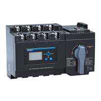
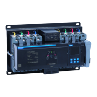
Visual inspection of the product and list of standard accessories provided with the automatic transfer switch.
Illustrates the steps for manual debugging, including switch positions for double off, normal on, and standby on.
Demonstrates power-on test scenarios in automatic, setting state, and generator start-up modes.
Provides detailed dimensions for NXZ series models (NXZ-125 to NXZ-630) and mounting hole specifications.
Illustrates wiring methods for 3-pole and 4-pole configurations, emphasizing correct N-pole wiring and conductor connections.
Details wire sectional area, width, number of conductors allowed, and torque for binding screws.
Diagrams and explanations for signal and control terminal wiring specifically for the Type A controller.
Illustrates typical wiring applications for Type B controllers and common usage scenarios in grid-power generation.
Step-by-step guide on how to install an isolation padlock for safety during maintenance operations.
Details the outline dimensions of the split-type display module and the required opening size for cabinet installation.
Provides a visual guide for the step-by-step installation of the split-type display module onto a cabinet surface.
Detailed description of the controller display interface, including indicators, buttons, and display areas for operation.
Guide to setting various parameters via the controller display module, including switching values, delays, and modes.
Details on setting communication address, baud rate, parity, data bits, and stop bits for the controller.
Flowcharts illustrating controller operation in automatic charge, automatic recovery (grid-grid), and grid-power generation modes.
Instructions and safety precautions for installing inter-phase flash barriers on the automatic transfer switch.
Lists common faults, their causes, and provides solutions for troubleshooting the automatic transfer switch.