This document provides user instructions for the CHINT NXZM and NXZ(H)M Automatic Transfer Switches (ATS), which comply with Standard IEC/EN 60947-6-1.
Function Description
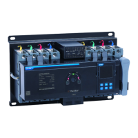
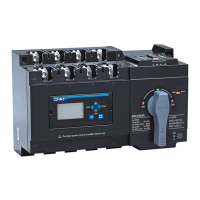
The CHINT NXZM and NXZ(H)M Automatic Transfer Switches are designed to automatically switch between a normal power supply and an alternative power supply (or generator) to ensure continuous power to a load. This is crucial for applications where an uninterrupted power supply is essential. The device monitors the voltage parameters of both power sources and initiates a transfer when a fault is detected in the primary source or when the primary source recovers.
The controller supports various operating modes, including:
- Automatic Charge and Automatic Recovery (Grid - Grid): The ATS automatically transfers to the alternative power supply upon normal power failure and returns to normal power upon its recovery.
- Automatic Charge and Automatic Recovery (Grid - Power Generation): Similar to Grid-Grid, but involves starting and stopping a generator as the alternative power source.
- Automatic Charge and No Automatic Recovery (Grid - Grid): The ATS transfers to the alternative power supply upon normal power failure but does not automatically return to normal power upon its recovery, requiring manual intervention.
Important Technical Specifications
General Application Information:
- Normal Application Temperature: -5°C to +40°C. For extended temperature ranges (-25°C to +70°C), consultation with the manufacturer is required.
- Altitude: For altitudes above 2000m, consultation with the manufacturer is required.
- Pollution Class: Class 3.
- Installation Category of Main Circuit: III.
- Enclosure Protection Class: IP20.
Product Models and Dimensions (Unit: mm):
| Product Model |
A |
B |
B1 |
B2 |
C |
D |
G |
L |
H |
H1 |
H2 |
M |
N |
| NXZM-63, 125 |
300 |
240 |
230 |
223 |
267 |
220 |
25 |
178 |
178 |
151 |
47 |
9 |
17 |
| NXZHM-63, 125 |
|
|
|
|
|
|
|
|
190 |
161 |
56 |
|
|
| NXZM-160 |
340 |
250 |
245 |
240 |
307 |
230 |
30 |
194 |
167 |
152 |
50 |
9 |
17 |
| NXZHM-160 |
|
|
|
|
|
|
|
|
195 |
180 |
|
|
|
| NXZM-250 |
390 |
250 |
367 |
240 |
357 |
230 |
35 |
225 |
181 |
155 |
49 |
9 |
17 |
| NXZHM-250 |
|
|
|
|
|
|
|
|
216 |
190 |
50 |
|
|
| NXZM-400, 630 |
535 |
334 |
464 |
342 |
475 |
304 |
44 |
304 |
|
198 |
66 |
11 |
26 |
| NXZHM-400, 630 |
|
|
|
|
|
|
|
|
234 |
|
|
|
|
| NXZM-800 |
660 |
344 |
477 |
344 |
600 |
314 |
58 |
385 |
|
203 |
68 |
11 |
26 |
| NXZHM-800 |
|
|
|
|
|
|
|
|
238 |
|
|
|
|
Wire Connection Dimensions (Unit: mm, Torque: N·m):
| Product Model |
a |
b |
c |
Torque |
| NXZM/NXZHM-63 |
8.0 |
17.5 |
6.5 |
4 |
| NXZM/NXZHM-125 |
|
|
|
|
| NXZM/NXZHM-160 |
7.5 |
16 |
8.5 |
10 |
| NXZM/NXZHM-250 |
10 |
23.5 |
8.5 |
12 |
| NXZM/NXZHM-400 |
10.5 |
30.5 |
11.5 |
30 |
| NXZM/NXZHM-630 |
|
|
|
|
| NXZM/NXZHM-800 |
15 |
43 |
14 |
40 |
Sectional Area, Width, and Number of Copper Wire (Unit: mm):
| Rated Current |
Cross-sectional area of copper wire or copper bar |
The number of copper wire or copper bar |
| 10 |
1.5 |
1 |
| 16 |
2.5 |
1 |
| 25 |
4.0 |
1 |
| 32 |
6.0 |
1 |
| 40 |
10 |
1 |
| 50 |
10 |
1 |
| 63 |
16 |
1 |
| 80 |
25 |
1 |
| 100 |
35 |
1 |
| 125 |
50 |
1 |
| 160 |
70 |
1 |
| 180 |
95 |
1 |
| 200 |
95 |
1 |
| 225 |
95 |
1 |
| 250 |
120 |
1 |
| 315 |
185 |
1 |
| 350 |
185 |
1 |
| 400 |
240 |
1 |
| 500 |
150 |
2 |
| 630 |
185 |
2 |
| 700 |
240 |
2 |
| 800 |
240 |
2 |
Default Parameter Settings for Display Module and Communication Function:
- Undervoltage Switching Value: Default 187V (user-settable 160V~200V).
- Overvoltage Switching Value: Default 263V (user-settable 240V~290V).
- Switching Delay: Default 5s (user-settable 0s~180s).
- Return Delay: Default 5s (user-settable 0s~180s).
- Generator Start-up Delay: Default 5s (user-settable 0s~180s).
- Generator Shutdown Delay: Default 5s (user-settable 0s~180s).
Usage Features
Installation and Wiring:
- Safety Warning: Installation and maintenance must be performed by professional technicians only. Installation in damp, condensed-phase, or explosive gas environments is forbidden. Touching conductive parts during operation is prohibited. The product should not be installed where gas medium can cause metal corrosion or insulation damage.
- Post-Installation Check: After installation, inspect the load side line and fire-resistance circuit. The controller must be set to "Manual" position and the product to "split position." Switch to "Auto" after line faults are eliminated.
- Wiring: The main power supply and voltage signal sampling line phase sequence must be consistent. Incorrect wiring of the voltage signal sampling line can damage the controller. Terminals 201 and 202 (signal and control terminals) should not have any electrical connection between them, as this can burn the controller. Terminals 501 and 502 should only be connected to a passive closing signal for fire control linkage; direct connection to any active signal will burn the controller. Strip at least 8mm of wire insulation before inserting into terminals.
- Display Module Installation: The display module can be installed on the cabinet door.
- Flash Barrier Installation: Flash barriers are provided for safety.
Controller Operation Interface:
The controller features a display and buttons for various functions:
- Indicators: Automatic working mode, manual working mode, failure (trip) indication, normal power breaker ON/OFF, alternative power breaker ON/OFF, setting condition, generator start signal, automatic charge/recovery mode, automatic charge/no recovery mode, generator mode, and communication status.
- Display Areas: Normal power voltage parameters, transfer delay time, alternative power voltage parameters.
- Buttons:
- Confirm/Return: Saves changes, exits setting mode, restores normal operation status in fire protection linkage mode.
- Compulsory Switch to Normal Power: In manual mode, switches to normal power if available. In setting mode, acts as "scroll up."
- Compulsory Switch to Alternative Power: In manual mode, switches to alternative power if available. In setting mode, acts as "scroll down."
- Off Button: In manual mode, switches to off position if either power line is normal. In setting mode, acts as "minus" for parameters.
- Failure Inquiry: Displays detailed malfunction codes when a failure occurs.
- Setting Button: Enters the parameter setting menu.
Parameter Setting:
The controller allows adjustment of various parameters, including undervoltage/overvoltage switching values, switching delay, return delay, generator start-up/shutdown delay, and communication settings (Modbus address and baud rate). These settings are accessed via the "SET" button and navigated using the up/down arrows, with "OK/Return" to confirm and exit.
Maintenance Features
Safety Warnings:
- Only professional technicians are allowed for maintenance.
- If a megameter with capacity over 500V is used to measure the insulation resistance of the circuit breaker, disconnect the secondary circuit of the controller first.
Product Troubleshooting:
The manual provides a troubleshooting guide for common and non-common faults:
Non-Common Faults and Solutions:
- Controller Display Failure: Press the Inquiry button to check for error codes (E-1 for normal power side trip, E-2 for alternative power side trip, E-3 for motor failure/disconnection). After resolving the fault, switch to manual mode, press the stop button or rotate the handle to stop position, then close. Confirm conversion by pressing Normal or Alternative button. If not convertible, repair or replace.
- Fire Control Linkage Still Active: After removing fire control linkage signals from terminals 501 and 502, switch the product to manual mode and press Confirm/Return to exit fire protection linkage mode.
- Failure to Switch to Faulty Power Supply: If the controller detects a fault, it will not switch to the faulty power supply automatically or manually unless a closing is forced with the handle.
- Failure to Automatically Transfer in Automatic Mode (Main Power Recovery): There is a +10V return value between undervoltage transfer value and recovery value, and a -10V return difference between overvoltage transfer value and recovery value. The recovery value for power supply must be greater than the total of transfer value and return value.
Common Faults and Solutions:
- Display Interface Not On After Powering Up:
- Poor contact at incoming line terminal: Ensure firm connection.
- Product not connected to neutral phase (3P product): Ensure firm connection.
- Controller fuse blown: Replace the fuse.
- Phase loss or failure: Check if the main circuit voltage is normal.
- Displayed Voltage of Phase A, B, and C Above 300V:
- One circuit of power supply not connected to neutral pole, or connected to live wire by mistake: Correct wiring according to instructions. Incorrect connection can burn the controller.
Environmental Protection:
To protect the environment, the product and its parts should be disposed of according to industrial waste treatment processes or sent to a recycling station for assortment, dismantling, and recycling in accordance with local regulations.