Model 108 Two Motor Tandem Installation Instruction
5
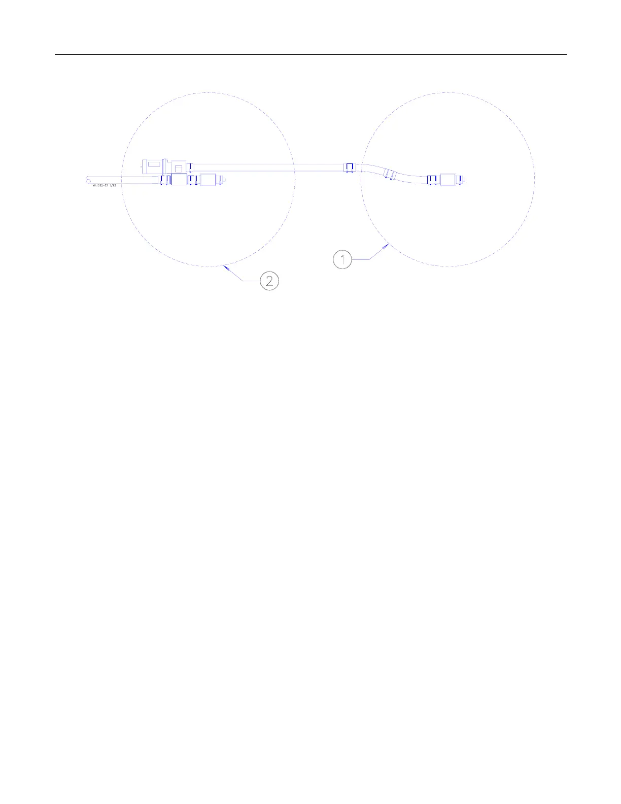
Key Description
1 Terminal Bin
2 Intermediate Bin
Figure 1.
Connecting the Bins
Assemble your Two Motor Tandem components as shown in Figure 2 or 3.
Steel systems; refer to Figure 2.
PVC systems; refer to Figure 3.
1. Secure the Connecting Boot directly to the Intermediate Bin Boot using a Tube
Connector w/clamps.
2. Install the Boot Support Assembly under the Connecting Boot to provide adequate
support.
3. Install an Adapter Plate on the bottom of the Control Unit, using the hardware
provided.
4. The 90° Elbow must be cut into (2) 22-1/2° Elbows. Refer to the FLEX-AUGER
Installation Manual for elbow cutting information.
5. Assemble the 22-1/2° elbows, straight pipe, Tube Connectors, Tube Inserts, PVC
Couplers, and clamps between the Terminal Bin Boot and the Connecting Boot.
6. Install and stretch the auger as specified in the Model 108 FLEX-AUGER Fill System
Manual.
7. Wire the Two-Motor Tandem system as specified in the wiring diagrams.
 Loading...

