17
Installation Testing
To identify potential damage, installation testing should be
completed at the following times:
• Prior to installing the heating cable
• Prior to installing the connection kits
• Prior to insulating the pipe
• After insulating the pipe
• Prior to energizing the cable
• During periodic system check-ups
• After maintenance/repair work
As part of the installation testing, complete the following
steps:
1. Visually inspect the heater cable and temperature con-
trols for signs of mechanical damage. If damage is seen,
either replace the complete heater cable, or cut out the
damaged section and replace using the proper splice
connection for the area and cable you are using.
2. Inspect all connections to be sure they are correctly as-
sembled. Be sure each heater cable entry to a connection
has a grommet and the compression plates and caps are
properly tightened.
3. Determine the insulation resistance of the circuit using at
least 1,000 VDC. It is strongly recommended that higher
test voltages be used. Polymeric cables (SR, SLL, and
CWM) should be tested at 2,500 VDC. Always perform
this test at the power connection. See Table 4 for mini-
mum insulation resistance readings. Any cable with an in-
sulation resistance below the recommended value should
be removed and factory should be contacted. See page
31 for a detailed explanation on how to conduct the insu-
lation resistance test.
4. Check voltage at the end of circuit and record in the log
on page 33. See page 31 for information on how to com-
plete the end of circuit voltage test.
Table 4 – Minimum Insulation Resistance Readings
Delivery
Installation
Pre-Insulation
Installation
Post-Insulation Maintenance
Chromalox SRL 20 MΩ 20 MΩ 5 MΩ 5 MΩ
Chromalox SRP 20 MΩ 20 MΩ 5 MΩ 5 MΩ
Chromalox SRM/E 20 MΩ 20 MΩ 5 MΩ 5 MΩ
Chromalox CWM 20 MΩ 20 MΩ 5 MΩ 5 MΩ
Chromalox MI
20 MΩ 20 MΩ 5 MΩ 5 MΩ
Chromalox SLL 20 MΩ 20 MΩ 5 MΩ 5 MΩ
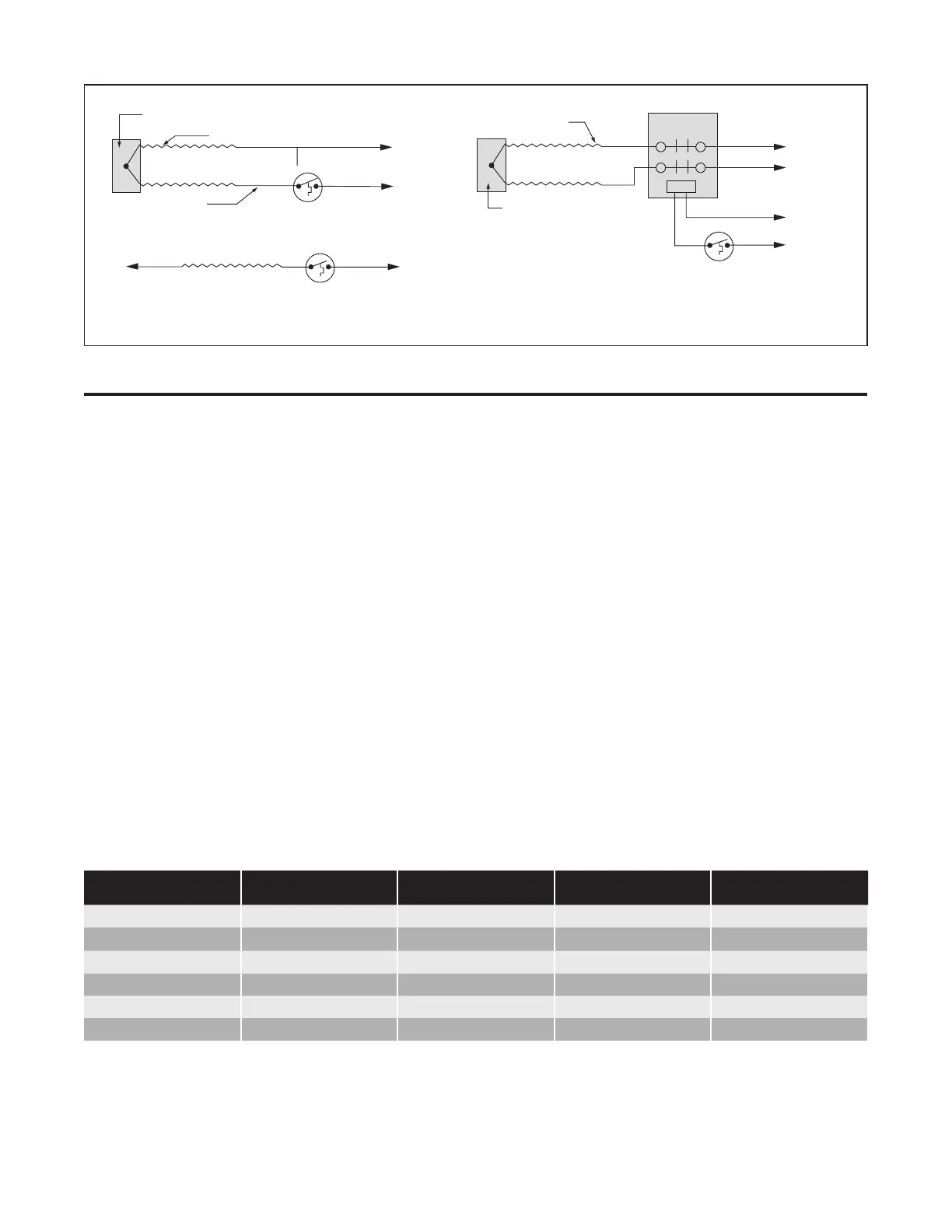
End Cap
End Cap
Cold Lead
Heat Resistance Wire
Heat Resistance Wire
Thermostat
Thermostat
Thermostat
L1
L1
L2
L2
Power Supply
Contactor
L1
L2
Power
Supply
Control
Circuit
OR
III. Mineral Insulated / Series Long Line
 Loading...