32
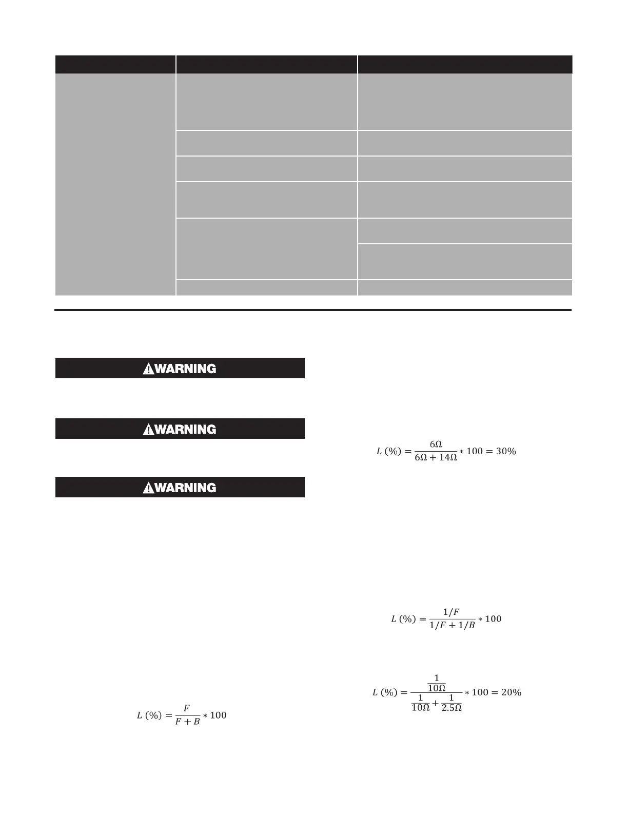
Observed Problem Potential Causes Corrective Actions
Circuit breaker trips
Undersized circuit breaker Check design to ensure startup temperature,
current loads, and maximum circuit length are not
exceeded, and that the power wire size is com-
patible with the circuit breaker. Replace circuit
breaker if necessary.
Startup temperature is too low Start up when temperature is higher than -76˚F
(-60˚C).
Damaged heating cable Replace damaged cable using the proper con-
nection kits.
Bus wires touching and shorting out Check for proper termination at end seal. Note
that the heating cable could be permanently dam-
aged and may need to be replaced.
Moisture Excessive moisture on heating cable core or bus
wires: Replace cable.
Moisture on connection kits: Retest after drying
out all components. Ensure all conduit entries are
properly sealed during reinstallation.
Undersized GFPD
Replace with appropriately sized GFPD.
Test Procedures
When testing any Chromalox heat trace product, al-
ways utilize the proper protective equipment and be
sure to comply with all applicable safety guidelines.
Before testing any Chromalox heat trace products,
ensure that all test equipment is working as intend-
ed and has been properly calibrated.
Only trained and qualified personnel should admin-
ister the test.
Locating Faults
The three most common test methods for finding the approx-
imate location of a fault in a heating cable are:
• Ratio test
• Conductance test
• Capacitance test
Ratio Test
The ratio test can be used to approximate the fault location
of a bus wire short or a fault from bus wire to ground braid. A
standard ohmmeter is used to take resistance readings from
both the front (F) and back (B) end of the cable. The fault lo-
cation (L) as a percentage of cable length measured from the
front end can be approximated by:
To determine a bus wire short, the resistance reading is taken
between the bus wires with one lead placed on each bus
wire. To determine a low resistance ground fault, the resis-
tance reading is taken between the bus wires and the braid
with one lead on bus wire and one on the braid.
Example: There is a bus wire short at an unknown point on
a 100ft cable. The resistance reading between the bus wires
is 6Ω from the front end of the cable and 14Ω from the back
end.
The bus wire short is approximated to be 30ft (30% of 100ft)
from the front end of the cable.
Conductance Test
The conductance test can be used to find the fault location
of a severed heating cable. A standard ohmmeter is used to
take resistance readings between the bus wires from both
the front (F) and back (B) end of the cable. The fault location
(L) as a percentage of cable length measured from the front
end can be approximated by:
Example: A 100 ft long heating cable is severed at an un-
known point. The bus-to-bus resistant reading is 10.0Ω from
the front end and 2.5Ω from the back end.
The cable is estimated to be severed at around 20ft (20% of
100ft) from the front of the cable.
 Loading...