33
Capacitance Test
The capacitance test can be used to estimate the length of
an intact heating cable or the fault location of a severed cable
that has passed the insulation resistance testing. A capaci-
tance reading is taken between the bus wires and the braid at
the end with the power connection. The bus wires should be
twisted together and connected to the positive lead, and the
braid should be connected to the negative lead. The fault lo-
cation can be found by multiplying the recorded capacitance
with the capacitance factor found in Table 25.
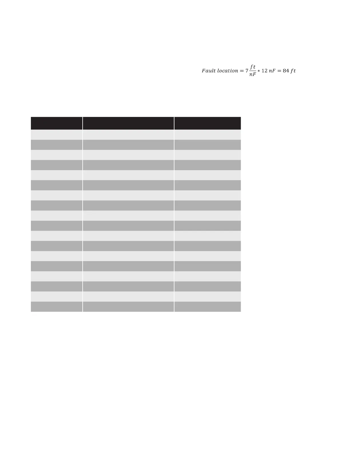
Example: A heating cable with a capacitance factor of 7 ft/
nF is severed at an unknown point. The capacitance reading
between the bus wires and the braid is 12 nF.
The cable is estimated to be severed at around 84ft from the
power connection.
Part
Number Description
Capacitance Factor
(ft/nF)
SRL3-1CR/CT 3 W / FT @ 50˚F - 120V 5.5
SRL3-2CR/CT 3 W / FT @ 50˚F - 208-277V 5.9
SRL5-1CR/CT 5 W / FT @50˚F - 120V 6.0
SRL5-2CR/CT 5 W / FT @ 50˚F - 208-277V 5.4
SRL8-1CR/CT 8 W / FT @ 50˚F - 120V 5.5
SRL8-2CR/CT 8 W / FT @ 50˚F - 208-277V 5.5
SRL10-1CR/CT 10 W / FT @ 50˚F - 120V 5.1
SRL10-2CR/CT 10 W / FT @ 50˚F - 208-277V 5.3
SRM/E5-1CT 5 W / FT @50˚F - 120V 7.5
SRM/E5-2CT 5 W / FT @ 50˚F - 208-277V 7.2
SRM/E8-1CT 8 W / FT @ 50˚F - 120V 7.5
SRM/E8-2CT 8 W / FT @ 50˚F - 208-277V 7.6
SRM/E10-1CT 10 W / FT @ 50˚F - 120V 7.4
SRM/E10-2CT 10 W / FT @ 50˚F - 208-277V 7.4
SRM/E15-1CT 15 W / FT @ 50˚F - 120V 7.9
SRM/E15-2CT 15 W / FT @ 50˚F - 208-277V 7.5
SRM/E20-1CT 20W / FT @ 50˚F - 120V 7.5
SRM/E20-2CT 20 W / FT @ 50˚F - 208-277V 7.2
Table 27 – Capacitance Factors
 Loading...