5
-
4
BRAKES
J9105-98
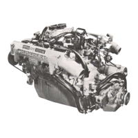
Fig,
8
Pump Assembly
Removal
(2)
Remove vacuum pump
from
adapter (Fig.
9).
Turn
pump
gear
back and
forth
to
disengage pump
shaft
from
coupling if
necessary.
(3)
Inspect adapter
O-ring
(Fig. 9). Replace
O-ring
if
cut or
torn.
COUPLING
O-RING
PUMP
ADAPTER
J9105-99
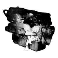
Fig,
9
Vacuum Pump Removed From Adapter
(4)
Lubricate adapter
O-ring
with
engine oil.
(5)
Note position of
drive
slots in
coupling.
Then ro-
tate drive
gear
to
align
tangs
on vacuum pump shaft
with
coupling
(Fig.
10).
(6)
Verify
that pump
is
seated
in adapter and cou-
pling.
(7)
Install
and
tighten pump attaching nuts
and
washers.
PUMP
ADAPTER
REPLACEMENT
(1)
Remove coupling
from
adapter (Fig. 11).
(2)
Remove remaining adapter attaching nuts and
remove adapter
from
steering pump (Fig. 12).
(3) If
steering pump
will
be serviced, remove
spacer
from
each inboard mounting stud on pump (Fig. 12).
(4)
Clean and lubricate pump shaft
with
engine
oil.
ROTATE
DRIVE
GEAR
TO
ALIGN
TANGS
J9105-102
Fig.
10
Aligning
Pump
Shaft
Drive
Tangs
Fig.
11
Removing/installing
Pump
Drive
Coupling
(5)
Install
spacers
on steering pump
studs
(Fig.
12).
(6)
Install
O-ring
on adapter
(Fig.
11).
(7)
Position adapter on pump studs.
(8)
Install
attaching nuts on outboard stud and on
the two upper pump studs. Do
not
install
nut
on
lower,
inboard stud
at
this
time.
Tighten nuts
to 24
N-m
(18 ft. lbs.) torque.
(9)
Install
coupling
on
pump shaft.
Be
sure
cou-
pling
is
securely engaged in shaft drive tangs.
 Loading...