INSTALLATION MANUAL---Installation of the Indoor unit
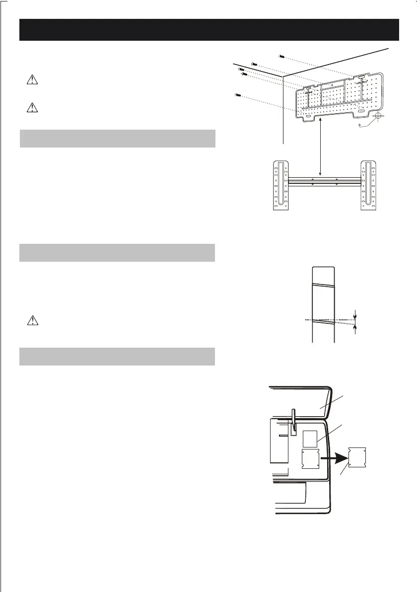
1. Using a level, put the mounting plate in a perfect
square position vertically and horizontally.
2. Drill 32 mm deep holes in the wall to x the
plate;
3. Insert the plastic anchors into the hole;
4. Fix the mounting plate by using the provided self-tapping
screws
5. Check that the mounting plate is correctly xed;
50
5mm
Note : Keep the drain pipe sloped in the direction
of the wall hole, otherwise water leakage may occur.
Before starting installation, determine on the position and location of the
indoor and outdoor units, taking into account the minim-
um space required around the units
Install the indoor unit in the room to be air conditio-
ned, avoiding to install in corridors or common
areas.
Install the indoor unit at a height of at least 2.5 m
from the ground.
To install, proceed as follows:
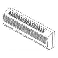
1. Decide where to drill the hole in the wall for the pip-
ing ( if necessary ) according to the position of the
mounting plate;
2. Install a exible ange through the hole in the wall to
keep the latter intact and clean.
The hole must slope downwards towards the exterior
Note : The shape of the mounting plate may be dierent
from the one shown, but installation method is similar .
Indoors
Outdoors
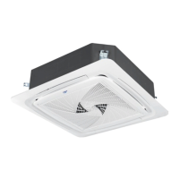
1. Lift the front panel.
2. Remove the terminal block cover as indicated in the picture
3. For the electrical connections, see the circuit diagram
on the right hand side of the unit under the front panel.
4. Connect the wires to the screw terminals by
following the numbering ,Use wire size suitable to
the electric power input (see name plate on the unit)
and according to all local safety code
requirements.
5. The cable connecting the outdoor and indoor units
must be suitable for outdoor use.
6. The plug must be accessible also after the appliance
has been installed so that it can be disconnected out if nece-
ssary.
7. A proper earth connection must be ensured.
8. If the power cable is damaged, it must be replaced by
an authorised Service Centre.
Front panel
Terminal block cover
wiring diagram
Note:The cable wires has been connected to the main
PCB of indoor unit by manufacturer according to the
model without terminal block
16
Installation of the mounting plate
Drilling a hole in the wall for the piping
Electrical connections---Indoor unit