C.I.B. UNIGAS - M03965CE
5
GENERAL FEATURES
The fuel coming from the supply line, is pushed by the pump to the nozzle and then into the combustion chamber, where the mixture
between fuel and air takes place and consequently the flame.
In the burners, the mixture bertween fuel and air, to perform clean and efficient combustion, is activated by atomisation of oil into very
small particles. This process is achieved making pressurised oil pass through the nozzle.
The pump main function is to transfer oil from the tank to the nozzle at required quantity and pressure. To adjust pressure, pumps are
provided with a pressure governor (except some models for which a separate adjusting valve is provided). Other pumps are provided
with two pressure governors: one for high and one for low pressure (in double-stage systems with one nozzle).
In the double-stage burners, the electric actuator, that moves the air damper, allows the optimisation of the gas flue values, as to get an
efficient combustion. The position of the combustion head determines the burner output. The air (comburent) and fuel (light oil) are for-
ced into the combustion chamber, as to let the flame light up.
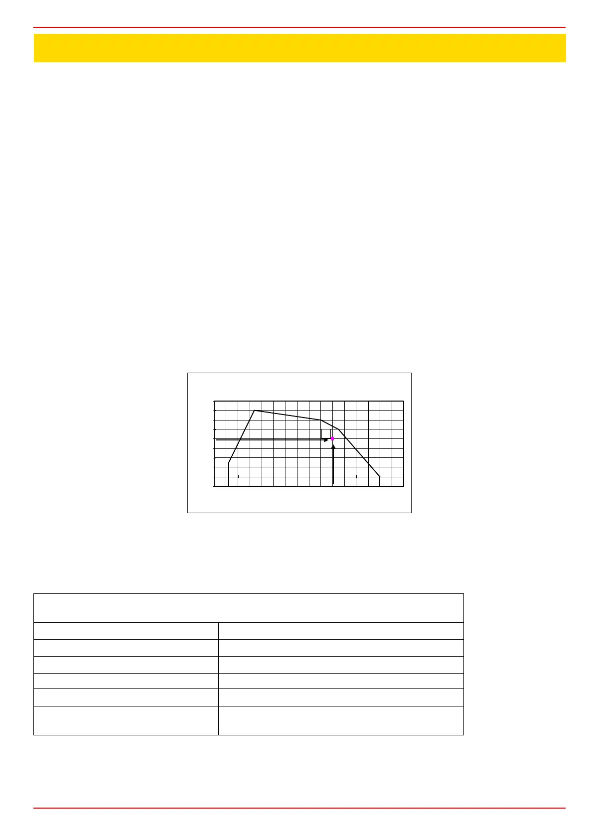
How to interpret the burner’s “Performance curve”
To check if the burner is suitable for the boiler to which it must be installled, the following parameters are needed:
z furnace input, in kW or kcal/h (kW = kcal/h / 860);
z backpressure (data are available on the boiler ID plate or in the user’s manual).
Example:
Furnace input: 600kW
Backpressure: 4mbar
In the “Performance curve” diagram (Fig. 1), draw a vertical line matching the furnace input value and an horizontal line matching the
backpressure value. The burner is suitable if the intersection point A is inside the performance curve.
Fig. 1
Data are referred to standard conditions: atmospheric pressure at 1013mbar, ambient temperature at 15°C
Burner model identification
Burners are identified by burner type and model. Burner model identification is described as follows.
Type PG60 Model G-. AB. S. *. A.
(1) (2) (3) (4) (5) (6)
(1) BURNER TYPE
PG30-PG60-PG70-PG81
(2) FUEL
G - Light oil A - Biodiesel
(3) OPERATION
AB - Double-stage
(4) BLAST TUBE S - StandardStandard L - Extended
(5) DESTINATION COUNTRY * - see data plate
(6) BURNER VERSION
A - Standard
M - With hydraulic ram
Campo di lavoro bruciatori
Tipo P60 Mod. M-xx.x.IT.A.0.50 - M-.xx.x.IT.A.0.65
-1
0
1
2
3
4
5
6
7
8
100 200 300 400 500 600 700 800 900
Potenza kW
Contropressione in camera di
combustione mbar
A
 Loading...