Cimco Series 21
CIMCO ELECTRONICS, INC. 26 MAIN STREET; P. O. BOX 248
www.cimcoelectronics.com WEST MIDDLESEX, PA 16159
E-MAIL: cimco@cimcoelectronics.com PHONE (724) 528-9559
FAX (724) 528-1108
Contact Cimco for details www.cimcoelectronics.com Operator Instructions-21-January 2002-Rev 4
Page 6 of 6
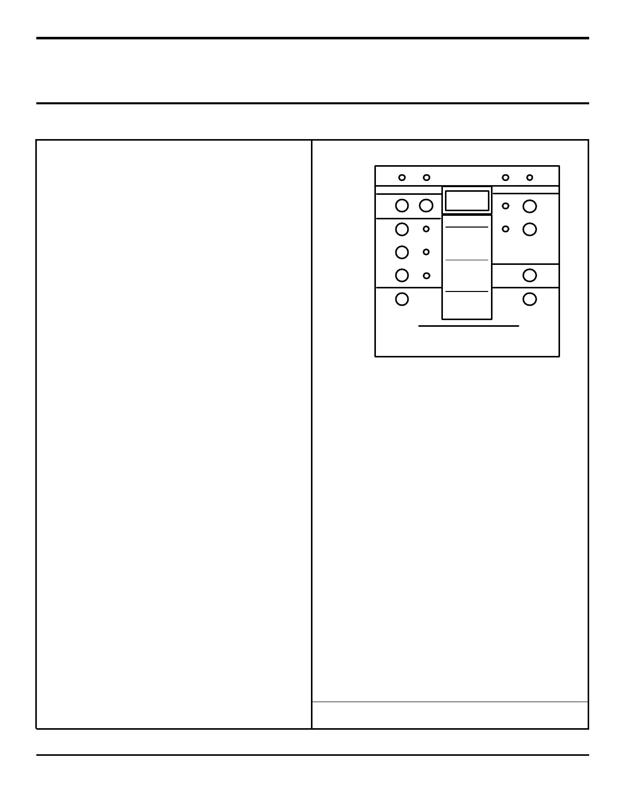
POWER ON FANS ON ALARM TRIP
OPERATING STATUS
DISPLAY CONTROL
OPERATION CONTROL
MAXIMUM
TEMP.
MEMORY
READ RESET
LEFT
PHASE
CENTER
PHASE
RIGHT
PHASE
AUTO
MANUAL
ON
FAN
MODE
CONTROL
PRESS AND HOLD
TO OPERATE SYSTEM TEST
PRESS AND RELEASE
TO ADVANCE TEST MODE
PRESS
TO
SILENCE
LOCAL
ALARM
SYSTEM TEST CONTROLS
TEST MODE SEQUENCE
1. INSTRUMENT AMBIENT
2. FANS ON
3. ALARM ON
4. TRIP ON
5. 4 TH SET-POINT ON - OPTION
6. 5 TH SET-POINT ON - OPTION
7. 5 TH SET-POINT OFF - OPTION
8. 4 TH SET-POINT OFF - OPTION
9. TRIP OFF
10. ALARM OFF
11. FAN OFF
TEMPERATURE °C
INSTRUMENT
AUTOMATICALLY
DISPLAYS PHASE WITH
HIGHEST TEMPERATURE.
PRESS PHASE BUTTONS
TO READ CURRENT
PHASE TEMPERATURES.
PRESS AND HOLD
"READ" BUTTON THEN
PRESS LEFT, CENTER OR
RIGHT PHASE BUTTON
TO READ MAXIMUM
TEMPERATURE MEMORIES
OF OTHER PHASES.
PRESS AND HOLD
LEFT, CENTER AND RIGHT
PHASE BUTTONS
TO READ
MATHEMATICAL AVERAGE
OF THREE INPUTS.
Operating Instructions for Monitoring Features
(continued)
11.
SYSTEM TEST (general description)
(for start-up test or check set-points and relays)
1. Reference Table 1 for test mode sequence.
2. Press and hold button 10 then (NOTE: User must
hold button 10 until desired steps in TABLE 1 are
complete.)
3. Press and release button 11 to advance TEST
MODE one step.
12.
SYSTEM TEST sequential actions of test mode are:
1. Instrument ambient temperature is displayed and
all other LED’s turn on.
2. Fans on set-point temperature is displayed
1. Fans on LED is turned on.
2. Fans relays are turned on.
3. Alarm on set-point temperature is displayed.
1. Alarm on LED is turned on.
2. Alarm relay is turned on.
3. Local alarm is turned on.
4. Local alarm can be silenced if desired.
4. Trip on set-point temperature is displayed.
1. Trip on LED is turned on.
2. Trip relay will not turn on.
3. Trip relay turns on only with input signal.
5. Optional fourth set-point on temperature is
displayed.
1. 100's decimal point is turned on.
2. Fourth set-point relay is turned on.
6. Optional fifth set-point on temperature is
displayed.
1. 10's decimal point is turned on.
2. Fifth set-point relay is turned on.
7. Optional fifth set-point off temperature is
displayed.
1. 10's decimal point will blink.
2. Fifth set-point relay will turn off.
8. Optional fourth set-point off temperature is
displayed.
1. 100's decimal point will blink.
2. Fourth set-point relay will turn off.
9. Trip off set-point temperature is displayed and trip
on LED will blink.
10. Alarm off set-point temperature is displayed.
1. Alarm on LED will blink.
2. Alarm relay will turn off or
3. Local alarm will turn off if not previously
silenced.
FIGURE 1
11. Fans off set-point temperature is displayed.
1. Fans on LED will blink.
2. Fan relays will turn off.
12. Standard default settings are:
1. Fans set-point on 190 degrees C
2. Alarm set-point on 200 degrees C
3. Trip set-point on 210 degrees C
4. 4
th
set-point on 230 degrees C
5. 5
th
set-point on 230 degrees C
6. 5
th
set-point off 220 degrees C
7. 4
th
set-point off 220 degrees C
8. Trip set-point off 200 degrees C
9. Alarm set-point off 190 degrees C
10. Fans set-point off 180 degrees C
13. Cimco Electronics can program special default
settings upon request.
***Reference Table 1 on page 4.***
Series 21-Monitoring Features
Drawing: 10-21-96-A
 Loading...