Note
Vehicle must be positioned on a flat
surface in order to position sensors
parallel with the road. Make sure that
sensors have an unobstructed “view” of
the road so the unit can function
properly. Do not install sensors behind a
solid surface, which would block laser
transmission/reception.
76
Individual Sensor Installation
Positioning Sensors
Install each sensor halfway between the
side and the center of the vehicle.
For optimal performance, sensors need to
be facing straight forward (or backward, if
installing optional rear sensors), not at an
angle.
Make sure that each sensor is parallel
with the road (using supplied bubble level).
Vehicle Sensor Installation Continued
80.00 mm
3.150 in
5.00 mm
0.197 in
9.75 mm
0.384 in
19.50 mm
0.768 in
19.50 mm
0.768 in
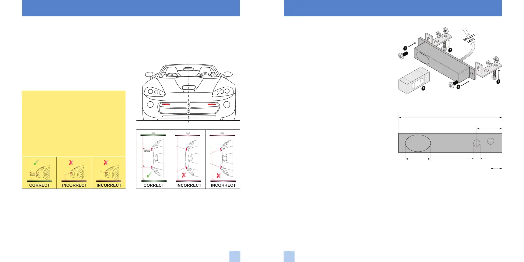
1 Using bolts, nuts and washers, mount
sensor to supplied L-shaped bracket and
tighten firmly.
2 Using screws, mount L-shaped bracket
(with sensor attached) to solid surface of
vehicle grill.
3 Use supplied bubble level to check
alignment of the sensor and ensure it is
parallel to the road.
4 Repeat for additional sensor(s).
If you must install sensors behind the front
grill of the vehicle, it is crucial that they be
positioned in such a way that the receiver
and transmitter components have
unobstructed “views” of the road. The
image at right shows the positions of both
the receiver and transmitter components
within the sensor. The 19.5 mm ellipse
(0.77 in) represents the receiver lens, while
the 5 mm (0.20 in) circle represents the
laser diode transmitter.
Securing Connectors with Shrink Tube
Once you’ve installed all components
properly and tested to ensure all parts are
working properly, it is advisable to use the
supplied heat-shrink tubes to protect
connectors against water, moisture, dust,
etc.
 Loading...