11. Install gasket (009) and packing box end cover (003) using bolts or capscrews (004). Tighten bolts or
capscrews (004) to proper torque valve listed in Table 3.
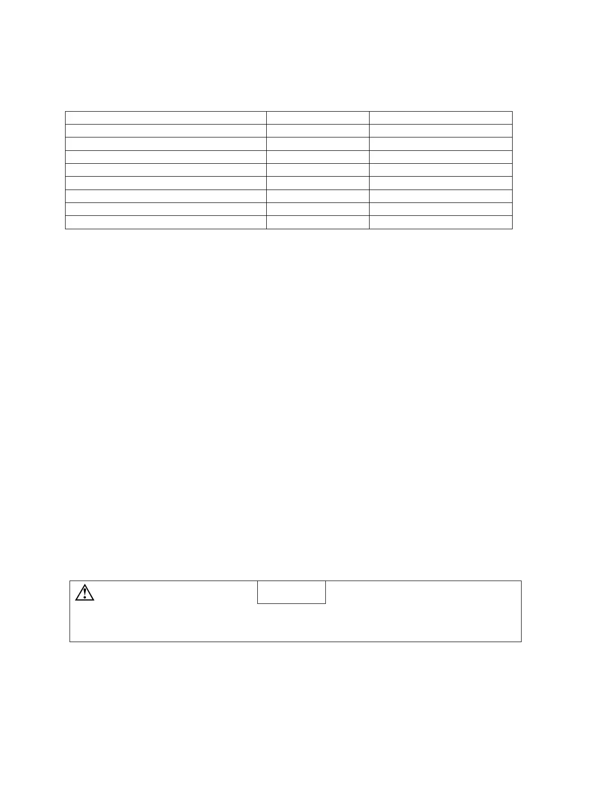
Table 3
TORQUE VALVES – PACKING PUMPS
Rotor Size IDP# Torque
106 (Installed in inlet) 4 43 ± 2 lb-ft
106 (Installed in packing box cove
) 4 24 ± 2 lb-ft
118 (Installed in inlet) 4 49 ± 2 lb-ft
118 (Installed in packing box cover) 4 26 ± 2 lb-ft
137 4 58 ± 2 lb-ft
156 4 64 ± 2 lb-ft
187 4 97 ± 2 lb-ft
275 4 78 ± 2 lb-ft
12. Install packing (017) rings in packing bore of packing box end cover (003). Joints of packing (017) ring
to be staggered and hard and soft rings alternately inserted, beginning with hard ring of packing.
13. Install packing gland (018). Install washer (015) and nut (016) on packing gland screw (014) and tighten
nut (016) hand tight.
14. Install idler rotors (021) into rotor housing (024) idler rotor bores by engaging threads of idler rotors with
threads of power rotor (019 or 063) and rotating idler rotors (021) while inserting them into rotor housing
(024).
15. Install idler balance piston housings (023) on idler rotors (021).
16. Install thrust cage (029), ensuring that bore in thrust cage (029) engages oil balance tube (026) installed
in rotor housing (024).
17. Install gasket (009) and inlet head (002) on case (001) using bolts or capscrews (004). Tighten bolts or
capscrews (004) to proper torque valve listed in Table 3.
18. Install key (031) and coupling hub on power rotor (019 or 063) shaft.
19. Install drain plugs (005 or 080).
20. (Figures 5 and 6) Install tubing (081) and fittings in proper position.
21. Connect pump to mounting bracket and coupling. Align pump with driver as described in Manual
CA-1.
Caution
When starting pump, adjust packing seepage to allow no more than eight (8) drops per
minute. DO NOT over-tighten packing. Seepage from packing gland provides cooling and
lubrication of packing
 Loading...