CVM-NRG96-ITF-BACnet-C
M98238701-03-15A
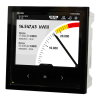
CVM-NRG96-ITF BACnet-C POWER ANALYZER
CVM-NRG96 is an instrument that measures, calculates
and displays the main electrical parameters in three-
phase industrial power grids (balanced or unbalanced).
The measurement is taken as an RMS value by three AC
voltage inputs and three AC current inputs. (through
current transformers, I
n
/5A /1A). The measured and
calculated parameters are shown in the table of variables.
This document provides the instructions for use and describes
the operation of the CVM-NRG96 analyzer. You can download
the manual from CIRCUTOR's web site in case it is misplaced:
www.circutor.com
You must disconnect the unit from all power
supplies before performing any
maintenance operati
ons, connection
modifications, repairs, etc. If you suspect
an operational fault in the unit or in its protection
system, remove the unit from service. The design of the
unit makes it easy to replace in the event of a fault.
1.- SETUP - Metering
To enter the metering setup menu, press the MAX and Min
keys for 5 seconds.
The
key validates the data and skips to the next
menu.
The MAX key can be used to select the different options in
the menu or to raise one digit if a variable is being
entered.
The MIN key is used to move the cursor between digits.
The various options are described below in sequence.
1.1.- Votage phase-phase or phase-neutral
This option allows to display the voltage phase to phase
or phase to neutral in the device:
a) SET U1/U2/U3: voltage phase to neutral
b) SET U12/U23/U31: voltage phase to phase
1.2.- Primary winding of the voltage transformer
set PriU: programming of the value of the primary winding
of the voltage transformer (from 1 to 100,000 volts).
1.3.- Secondary winding of the voltage
transformer
SET seco: programming of the value of the secondary
winding of the voltage transformer (from 1 to 999 volts).
1.4.- Primary winding of the current transformer
SET PriA: programming of the value of the primary winding
of the current transformers between 1...10,000 amps.
1.5.- Secondary winding of the current
transformer (ver. ../5A ../1A)
SET SECA: choose the value of the secondary winding of
the current transformers between 5 or 1 amps.
1.6.- Programming the maximeter:
a) SET Pd Code xx: select the electrical variable to be
integrated by means of the system of maximum
demand in sliding window:
Apparent Three-phase Power
b) Pd Per: value of the integration period of maximum
demand, in a period that can be configured between
1...60 minutes
c) CLr Pd no: deletion of the maximum value of maximum
demand registered (no / YES)
1.7.- Initial start screen programming
seT iniT page: this option is used to select the screen and
form of selecting the display screens:
a) Fixed page: this is used to select which of the pages
available will appear first of all when powering up
the analyzer.
b) Rotating screens: selecting the rotating screens
option (when all electrical magnitudes are flashing),
will begin automatic page rotation, where each
page is displayed every 5 seconds.
1.8.- Initial start energy selection
seT iniT page: this option is used to select the energy
displayed in the device. The user must select from the
following energy meters (consumed or generated “-“):
- Active energy: kW·h
- Reactive inductive energy: kVArL·h
- Reactive capacitive energy: kVArC·h
Apparent energy: kVA·h
1.9.- Backlighting time
diSP oFF: disconnection time of the display backlighting
after pressing any key on the analyzer (1...60 seconds).
When programming 00, the backlighting remains on
permanently.
1.10.- Resetting energy meters
CLr EnEr: resetting the energy values (no / YES)
1.11.- THD or d Programming
SET HAr d: this is used to select a method for calculating
the voltage and current harmonic distortion:
a) d: % harmonic distortion with respect to fundamental
(voltage and current).
b) Thd: % harmonic distortion with respect to the RMS
(voltage and current).
1.12.- Digital output (C)
Out 1 CodE :The digital output can be programmed for:
Generate energy impulses: the kW.h corresponding to one
impulse (100 ms) and a maximum 5 imp/s (see variable
codes) is programmed using one of the energy codes.
Alarm conditions: the instant variable controlled, maximum,
minimum values and delay for the output is programmed
(see variable codes).
2.- SETUP - Communication
To enter the communication menu of the unit, press the
RESET key and then press
, MAX and Min for five
seconds until you enter the communication setup.
The configuration parameters for the device are:
a) SET PROT: Bac (BacNet)
b) Set def: no (custom), YES (default configuration*)
c) Set mac: peripheral no. 001 to 127
d) SET bAud: (speed) 9.6-19.2-38.4-76.8-115.2
e) SET Id: (Device_ID)
f) Set loc: unlo (unlocked), Loc (locked)
*
Default configuration: 002 / 38400
2.1.- SETUP - locking or unlocking
By choosing the Loc option, on entering metering SETUP,
it is only possible to see the programming, no parameter
can be changed. When the
LOC option is activated, the
password 1234 must be entered to edit the programming of
the unit.
VARIABLES AND ALARM CODES
If no variable is to be programmed, select 00
Reactive power -(Ind/Cap)
Three-phase inductive power
Three-phase capacitive power
Inductive reactive energy
Capacitive reactive energy
Inductive energy generated
Capacitive energy generated
Apparent energy generated
*These variables are only valid when the maximum current demand per phase has been
programmed.
The analyzer has variables that refer to the three phases simultaneously. If these
variables are selected, the unit makes an OR type logical function, activating the alarm
flag when any of the three phases meets the triggering conditions.
METERING IN FOUR QUADRANTS
Power