Do you have a question about the Cisco MERAKI MS120-8FP and is the answer not in the manual?
Guides users through initial setup steps for adding a switch to a Meraki Dashboard network.
Recommends upgrading switch firmware immediately after installation for optimal performance.
Advises on necessary firewall configurations for proper switch operation and cloud connectivity.
Explains how to configure DHCP servers to assign static IP addresses to Meraki switches.
Details the procedure for manually assigning static IP addresses to a switch via its web server.
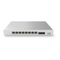
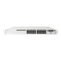
The Cisco Meraki MS120-8 series switches are Layer-2 gigabit Ethernet devices designed for network connectivity. This guide provides comprehensive instructions for their installation, configuration, and basic troubleshooting, ensuring a smooth setup process for various network environments. The switches are engineered to integrate seamlessly into existing Meraki networks, offering a robust and manageable solution for businesses.
The MS120-8 series switches serve as the backbone for local area networks, facilitating high-speed data transfer between connected devices. As Layer-2 switches, they operate at the data link layer of the OSI model, forwarding Ethernet frames based on MAC addresses. This ensures efficient communication within the local network segment. The switches come in three main models: the MS120-8, MS120-8LP, and MS120-8FP. The MS120-8 is a standard 8-port gigabit Ethernet switch with 2 SFP interfaces, suitable for general networking needs. The MS120-8LP is an 8-port gigabit Ethernet switch with 67W Power over Ethernet (PoE) capabilities and 2 SFP interfaces, ideal for powering devices like IP phones, wireless access points, and security cameras directly through the Ethernet cable. The MS120-8FP offers enhanced PoE capabilities with 124W PoE across its 8 gigabit Ethernet ports and 2 SFP interfaces, catering to environments with higher power demands for connected PoE devices. The SFP interfaces on all models allow for flexible uplink options, supporting fiber optic connections for longer distances or higher bandwidth requirements, extending the network's reach and performance.
The switches are designed to be managed through the Meraki cloud dashboard, providing a centralized platform for network configuration, monitoring, and troubleshooting. This cloud-based management simplifies network administration, allowing for remote access and control from anywhere with an internet connection. The dashboard enables administrators to configure port settings, VLANs, QoS policies, and other network parameters with ease. Firmware upgrades are also managed through the cloud, ensuring that the switches always run the latest software with the most up-to-date features and security patches. This automated approach to firmware management reduces manual effort and potential errors.
The MS120-8 series switches offer a range of usage features that enhance network performance and simplify deployment. The integrated mounting slides on the MS120-8 models facilitate a one-step mounting process, making physical installation quick and straightforward. This design consideration aims to reduce installation time and complexity, especially in environments where multiple switches need to be deployed.
Before physical installation, it is recommended to configure the dashboard network. This involves logging into the Meraki dashboard, creating a new account if necessary, and adding the switches to the network. Switches can be added using their Meraki order number or serial number, along with an Enterprise license key. Once added, administrators can visually place the switches on a map or floor plan within the dashboard, aiding in network visualization and management. This geographical representation helps in understanding the physical layout of the network and quickly identifying the location of each device.
A crucial pre-installation step involves checking and setting the firmware. Upon connecting the switch to power and a wired internet connection, the power LED will glow solid orange. If a firmware upgrade is required, the LED will blink white until the upgrade is complete, at which point it will turn solid white. This process ensures that the switch operates with the latest software, optimizing performance and security from the outset. Depending on the internet connection speed, the firmware upgrade may take several minutes.
For network connectivity, switches must be assigned routable IP addresses, either dynamically via DHCP or statically. When using DHCP, it is advisable to configure the DHCP server to assign a static IP address for each MAC address of the Meraki switch. This ensures consistent IP addressing, which is beneficial for features like 802.1X authentication. For static IP assignment, the local web server on each switch can be accessed via a wired connection. By browsing to http://my.meraki.com or http://1.1.1.100, administrators can access the "Uplink Configuration" tab. The default login uses the switch's serial number as the username and no password. Here, the static IP address, net mask, gateway IP address, and DNS servers can be configured. Alternatively, static IPs can be assigned via DHCP reservations on the upstream DHCP server, reserving specific IP addresses for the MAC addresses of the Meraki switches.
The front panel of the switches features LED indicators that provide real-time status updates. The power LED indicates the switch's operational status: solid orange means it cannot connect to the Meraki cloud, flashing white indicates a firmware upgrade in progress, and solid white signifies full operation and connection to the Meraki cloud. If the power LED is off, the switch does not have power. For switch ports, an off LED means no link is detected, flashing orange (for RJ45 ports only) indicates activity, and solid green signifies a 1 Gbps link. These indicators allow for quick visual assessment of the switch's health and connectivity.
Maintenance of the MS120-8 series switches is designed to be straightforward, primarily leveraging the cloud-managed architecture and built-in diagnostic tools. The Meraki dashboard provides continuous monitoring of the switch's status, performance, and connectivity, alerting administrators to any potential issues. This proactive monitoring helps in identifying and resolving problems before they impact network operations.
A key maintenance feature is the factory reset button, located on the front panel. This button serves two primary functions. A brief, momentary press will delete any downloaded configuration and reboot the switch, allowing for a quick reset to a clean state without losing factory defaults. Pressing and holding the button for at least five seconds will force the unit into a full factory restore, deleting all configuration information stored on the unit and reverting it to its original factory settings. This is particularly useful for troubleshooting persistent configuration issues or preparing the switch for redeployment.
Basic troubleshooting steps are also outlined to address common connectivity issues. These include resetting the switch, performing a factory reset by holding the button for five seconds, and trying different cables or testing existing cables on another device to rule out cable faults. If issues persist, the Meraki documentation website offers additional troubleshooting tips and resources. For hardware-related problems that cannot be resolved through basic troubleshooting, Cisco Meraki support can be contacted through the dashboard's "Help" option, allowing administrators to open an email case or call for assistance.
The equipment is designed for use in restricted access locations and should be installed and operated by trained service personnel. This ensures proper handling and adherence to safety guidelines. The product relies on the building's installation for short-circuit (overcurrent) protection, with protective devices rated no greater than 15A, 125 Vac, or 10A, 240 Vac. It is crucial to use only the provided power cables to ensure regulatory compliance and safe operation.
For storage and transportation, the equipment should be kept in its original packaging in a room protected from atmospheric precipitation, within the permissible temperature and humidity ranges specified in the Operation (Installation) Manual. Transportation should also occur in covered vehicles, adhering to the specified temperature and humidity ranges to prevent damage.
The MS120-8 series switches are intended for industrial or other commercial activities and are not for domestic use. They are designed for operation without the constant presence of maintenance personnel, but installation and maintenance should be performed by specialists with appropriate qualifications. Disposal of the technical device at the end of its service life must comply with all state regulations and laws, and it should not be disposed of with household waste. The organization's disposal procedure should be followed for proper storage and disposal.
Warranty information is also provided, with MS120-8 series switches typically covered by a lifetime warranty, while accessories like SFP modules, cables, and mounting kits have a 1-year warranty. In case of a hardware failure under warranty, Meraki support can process an RMA and provide a replacement device, often with a pre-paid shipping label for returning the faulty equipment. Access to the original packaging, including the serial number and order information, may be required for hardware replacement.
| Brand | Cisco MERAKI |
|---|---|
| Model | MS120-8FP |
| Category | Switch |
| Language | English |