14 Cisco 4000 Series Rack-Mount and Wall-Mount Installation
Overview of Telco Rack-Mounting and Wall-Mounting
Installing Telco Rack-Mount or Wall-Mount Brackets into a New Version of the Chassis
Take the following steps to install telco rack-mount or wall-mount brackets into the new version of
the chassis:
Step 1 Remove the component tray from the system. Refer to the procedure described in the
section, “Preparing the Chassis for Rack-Mounting or Wall-Mounting.”
Step 2 Insert one rack-mount bracket into the slot on each side of the chassis shell, lining up the
bracket with the screw holes located on the side of the chassis shell.
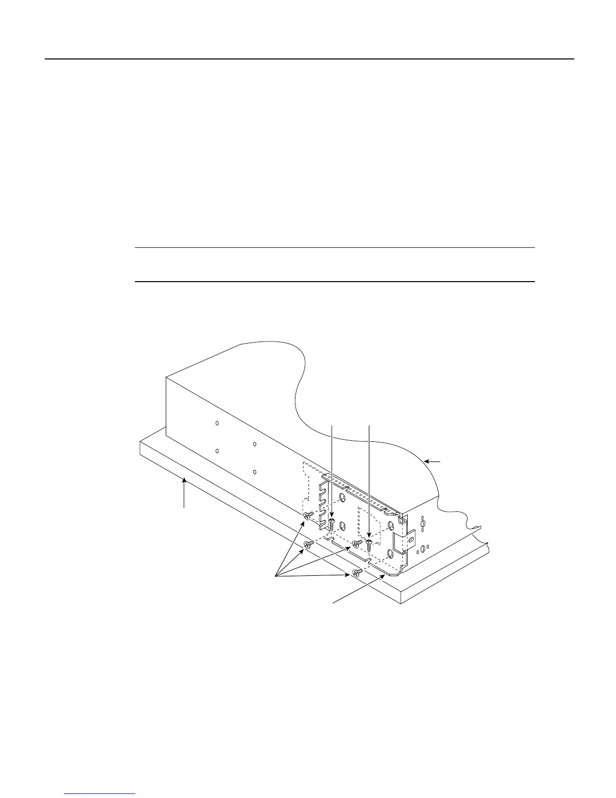
Step 3 Fasten each bracket to the side of the chassis shell using four 8-32 flat-head machine screws
(as shown in Figure 15).
Note Figure 15 shows screw locations for both telco rack-mounting and wall-mounting. The wood
screw locations apply only to the wall-mount procedures.
Figure 15 Screw Locations for Telco Rack-Mount or Wall-Mount Brackets – New Version of the
Chassis
Front of the chassis
H5966
Telco rack-mount or
wall-mount bracket
8-32 flat-head
machine screws
Chassis shell
19 x 19" or larger plywood
board (if wall-mounted)
Wood screws

 Loading...


