16
Removing and Replacing Memory SIMMs and the Boot ROM
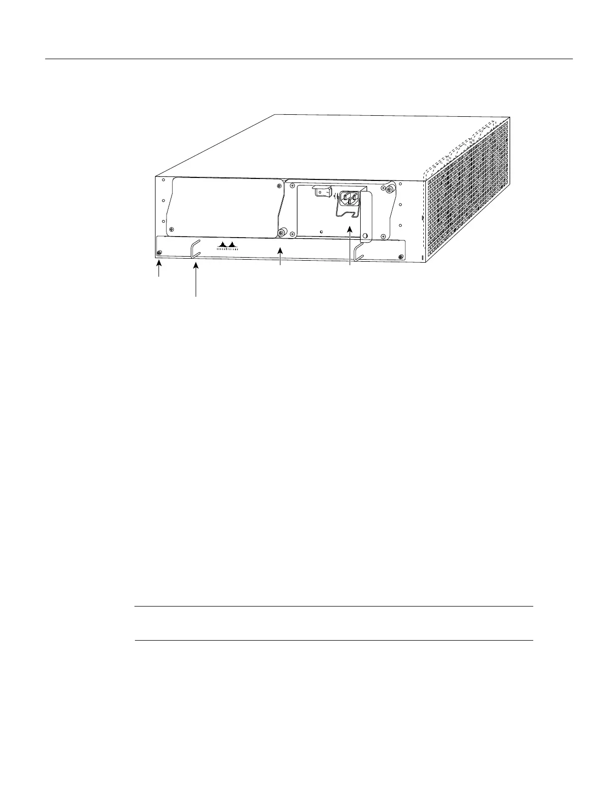
Figure 12 Cisco 7200 Series Network Processing Engine Captive Screws and Handles
Step 8
Place the network processing engine on an antistatic surface with its printed circuit board
components facing upward, or in a static shielding bag.
This completes the procedure for removing the network processing engine. Proceed to the section
“Removing Memory SIMMs.”
Removing Memory SIMMs
This section explains how to remove memory SIMMs that are installed on the I/O controller and the
network processing engine. To remove the installed SIMMs, complete the following steps:
Step 1 Attach an ESD-preventive wrist strap between you and an unpainted router surface.
Step 2 Place the I/O controller or the network processing engine on an antistatic mat or surface
(ensure that you are wearing an antistatic device, such as a wrist strap).
Step 3 Position the I/O controller or the network processing engine so that the handle is away
from you and the edge connector is toward you.
Step 4 Locate the SIMMs.
• The Flash SIMM on the I/O controller occupies socket U99 (refer to Figure 5).
• The DRAM SIMMs on the network processor engine occupy sockets U18, U25, U4,
and U12 (refer to Figure 6).
Note SIMMs installed in your system might look different from the SIMMs shown in the following
illustrations.
H6540
Captive
installation
screw
Handle
NETWORK PROCESSING ENGINE-150
Network processing
engine
AC-input
power supply
NPE-150

 Loading...


