Note With the I/O controller or the network processing engine in the same orientation as the
previous procedure (with the handle away from you and the edge connector toward you), you will
install the first SIMM in the socket farthest from you. Then you will install the last SIMM in the
socket closest to you.
Step 1 Remove a new SIMM from the antistatic bag.
Caution To prevent DRAM errors and to ensure your system initializes correctly at startup, DRAM
bank 0 (socket U25 and U18) must contain two SIMMs of the same type. You may also install up to
two SIMMs of the same type in bank 1 (socket U12 and U4); however, bank 0 must always contain
two SIMMs.
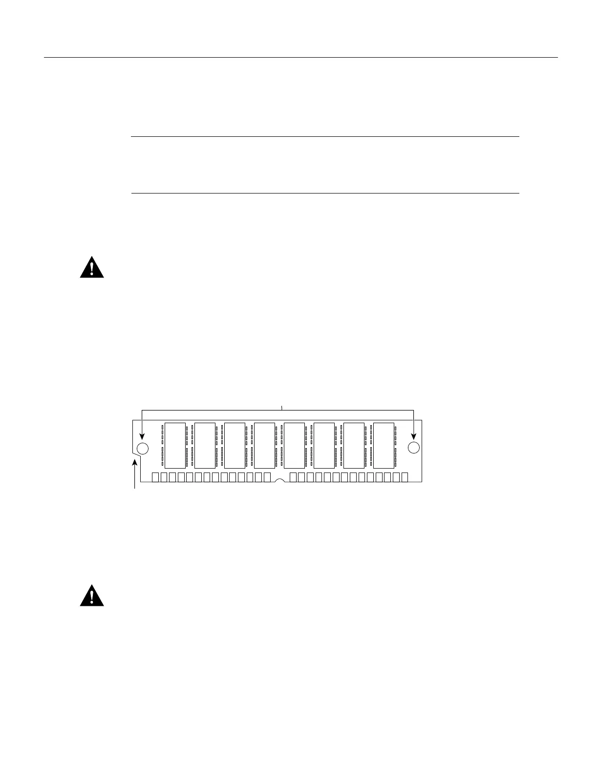
Step 2 Orient the SIMM so its connector edge (the metal fingers) is down and the component
side is facing you (refer to Figure 14).
Figure 14 Cisco 7200 Series Main Memory SIMM
Step 3
Hold the sides of the SIMM between your thumb and middle finger, with your forefinger
against the far edge, opposite the connector edge. (See Figure 9.)
Step 4 Tilt the SIMM to approximately the same angle as the socket and insert the entire
connector edge into the socket.
Caution When inserting SIMMs, use firm but not excessive pressure. If you damage a socket, you
must return the I/O controller or the network processing engine to the factory for repair.
Step 5 Gently push the SIMM into the socket until the spring clips snap over the ends of the
SIMM. If necessary, rock the SIMM gently back and forth to seat it properly.
Step 6 Repeat Steps 1 through Step 5 for the remaining SIMMs.

 Loading...


