23
Removing and Replacing Memory SIMMs and the Boot ROM
Step 3 Using both hands, grasp the network processing engine by its metal carrier edges and
orient the network processing engine so that its printed circuit board components are
upward (you can see the components) (refer to Figure 8).
Caution Handle the network processing engine by the carrier edges and handles only; never touch
the printed circuit board components or connector pins.
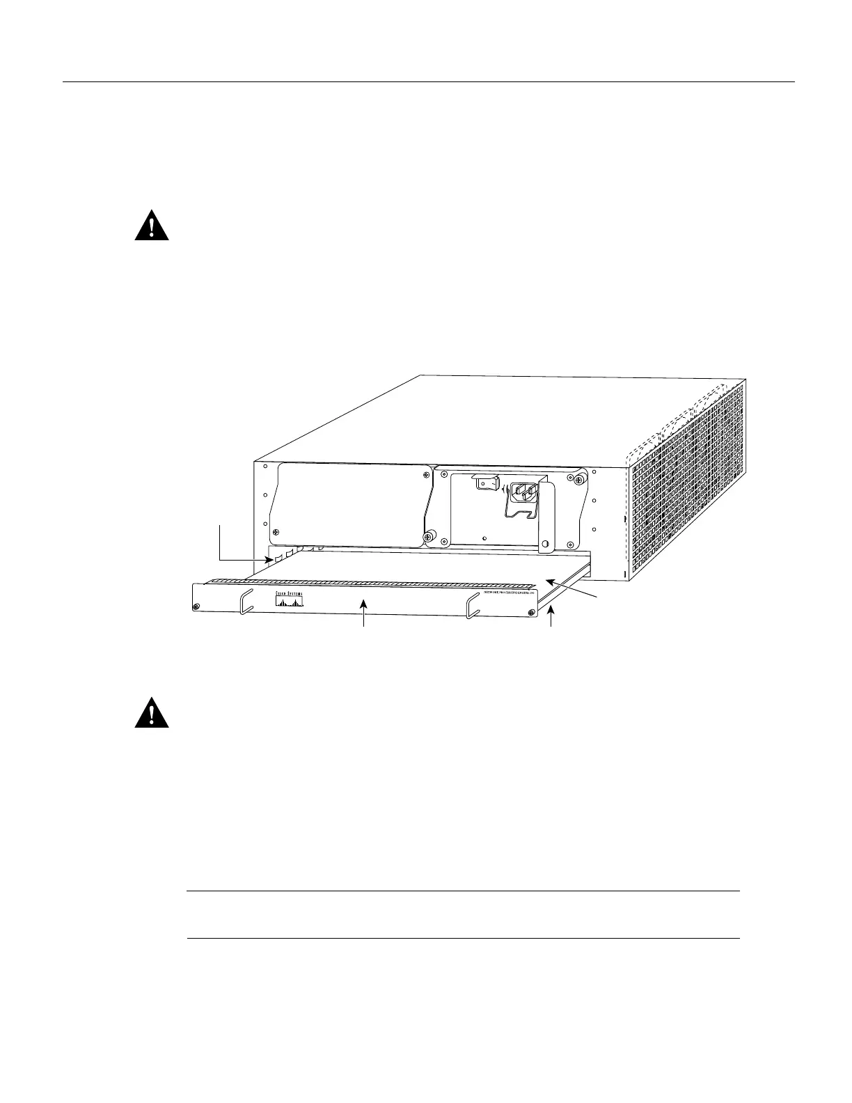
Step 4 Align the left and right edge of the network processing engine’s printed circuit board
between the network processing engine slot guides (refer to Figure 20).
Figure 20 Aligning the Network Processing Engine between the Slot Guides
Caution
Do not align the network processing engine’s metal carrier between the slot guides. Doing
so will damage components on the network processing engine’s printed circuit board as you slide
the network processing engine into its chassis slot.
Step 5 Gently slide the network processing engine all the way into its chassis slots until you feel
the connectors mate with the router midplane.
Step 6 Seat the network processing engine in the router midplane by tightening its captive
installation screws with a number 2 Phillips screwdriver.
Note The network processing engine is not fully seated in the router midplane until you tighten its
captive installation screws (use number 2 Phillips screwdriver).
Step 7 If you removed power supplies from the router, replace the power supplies. Refer to the
section “Removing and Installing an AC-Input Power Supply” on page 28 of this
document when replacing an AC-input power supply in a Cisco 7200 series router.
H6541
Metal carrier
Slot guides
Network processing
engine
Printed circuit board

 Loading...


