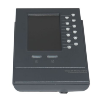
No Display on the 7916 Expansion Module
• Verify that all of the cable connections are
correct
• Verify that you have power to the 7916
Expansion Module
Buttons on the first 7916 Expansion Module are
all Amber
• Verify that the interface cable between the
7975 Phone and the 7916 Expansion
Module is connected.
• Verify with your system administrator that
your 7916 Expansion Module is defined in
Cisco Unified Communications Manager.
Buttons on the second 7916 Expansion Module
are all Amber
• Verify with your system administrator that
your 7916 Expansion Module is defined in
Cisco Unified Communications Manager.
Buttons are off, and the Cisco logo is frozen in the
display area
• Verify with your system administrator that
your 7916 Expansion Module is defined in
Cisco Unified Communications Manager.
The page shift button does not display the second
page
• Verify with your system administrator that
your 7916 is configured as a 24-line
module instead of a 12-line module in
Cisco unified Communications Manager.
The following are the cable specifications for the cables used with the Cisco Unified IP Expansion Module
7916:
• 2 RJ-11 jacks with 6-pin connectors for the interface cable connections
• 48-V power connector. The diameter of the center pin in the Expansion Module power jack
(Switchcraft 712A) is 0.1 in. (2.5 mm). The center pin is positive (+) voltage. The miniature power
plug required to mate with the power jack on the Expansion Module is a switchcraft 760 or
equivalent.