b. Position a slider rail at the desired level side of the rack and use two 12-24 screws or two 10-32 screws, depending
on the rack thread type, to attach the slider rail to the rack. Tighten the 12-24 screws to 30 in-lb (3.39 N·m) of torque,
or tighten the 10-32 screws to 20 in-lb (2.26 N·m) of torque.
c. Repeat Step 2 to attach the other slider rail to the other side of the rack.
To make sure that the slider rails are at the same level, you should use a level tool or tape measure, or carefully count
the screw holes in the vertical mounting posts.
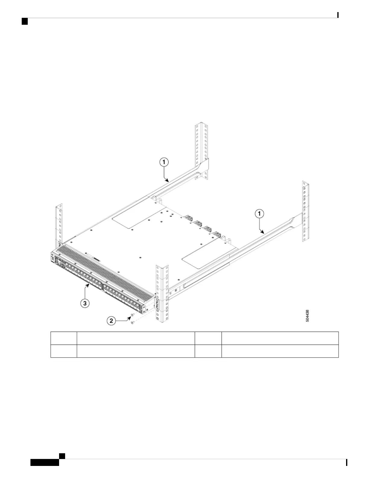
Step 4 Insert the switch into the rack and attach it as follows:
Chassis3.Slider rails1.
rack-mount screws2.
a. Holding the switch with both hands, position the two rack-mount guides on the switch between the rack or cabinet
posts that do not have slider rails attached to them.
b. Align the two rack-mount guides on either side of the switch with the slider rails installed in the rack. Slide the guides
onto the slider rails, and then gently slide the switch all the way into the rack until the brackets come in contact with
two rack or cabinet posts.
If you attached a grounding cable to the chassis, you will need to flex one of the rack-mount posts slightly
to allow the grounding lug to go behind the post.
Note
Installing the Cisco MDS 9148V-K9 Switch
8
Installing the Cisco MDS 9148V-K9 Switch
Installing the Switch in a 4-Post Rack
 Loading...