Maintenance and Upgrade Procedures for the ASA 5500-X
Remove and Install the Power Supply
Cisco ASA 5512-X, ASA 5515-X, ASA 5525-X, ASA 5545-X, and ASA 5555-X Hardware Installation Guide
63
3. From the front of the chassis, verify that the power switch is in the Standby position.
4. Move the circuit-breaker switch handle to the Off position, and apply tape to hold it in the Off position.
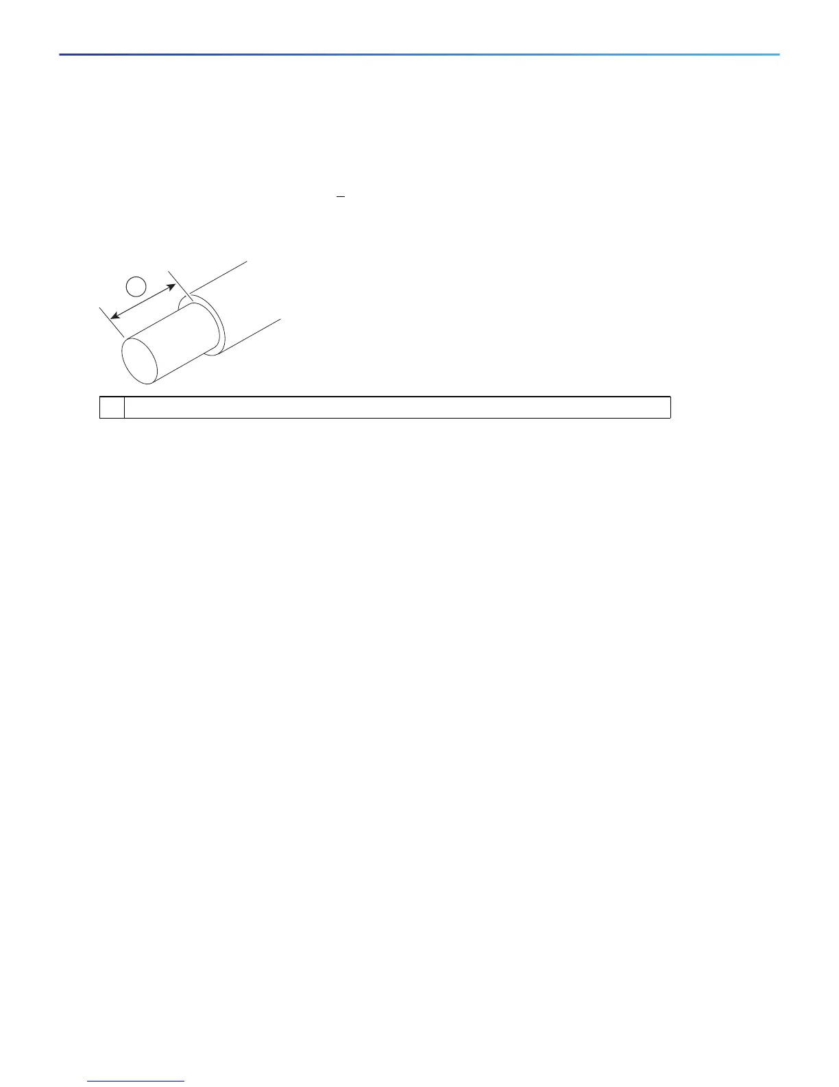
5. Use a 10 gauge wire-stripping tool to strip each of the three wires coming from the DC input power source.
Strip the wires to 0.27 inch (7 mm) +
0.02 inch (0.5 mm). Do not strip more than the recommended length of
wire because doing so could leave the wire exposed from the DC power supply connection. (See Figure 22.)
Figure 22 Stripping the DC Input Power Source Wire
Warning: An exposed wire lead from a DC input power source can conduct harmful levels of electricity. Be
sure that no exposed portion of the DC input power source wire extends from the terminal block plug.
Statement 122
6. Identify the positive, negative, and ground feed positions for the DC power supply connection. The
recommended wiring sequence is as follows (see Figure 23 on page -64):
— Ground lead wire (middle)
— Positive (+) lead wire (left)
— Negative (–) lead wire (right)
1 We recommend that you strip the wire to 0.27 inch (7 mm).
333062
1
 Loading...


