Maintenance and Upgrade Procedures for the ASA 5500-X
Remove and Install the Power Supply
Cisco ASA 5512-X, ASA 5515-X, ASA 5525-X, ASA 5545-X, and ASA 5555-X Hardware Installation Guide
64
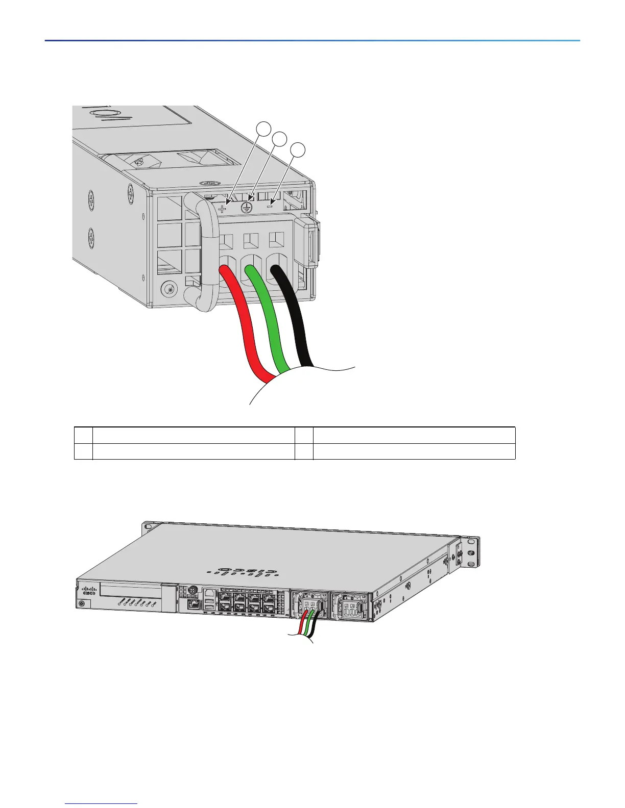
Figure 23 Color-coded Wires
Figure 24 shows the DC power supply with lead wires.
Figure 24 DC Power Supply with Lead Wires
7. Insert the exposed end of one of the ground wires into the inlet on the DC power supply. After you push in the
wires, they are held in place with a spring, which makes the physical contact. Make sure that you cannot see
any wire lead. Only wires with insulation should extend from the DC power supply.
8. Repeat Step 7 for the remaining two DC input power source wires: the positive lead wire and the negative lead
wire.
1 Negative (–) lead wire 2 Ground lead wire
3 Positive (+) lead wire
 Loading...


