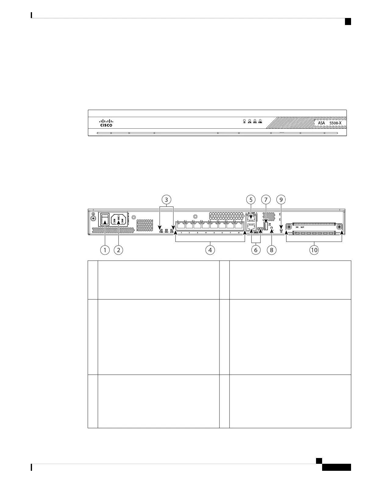
Front Panel
The following figure shows the front panel of the ASA 5508-X. The ASA 5516 has an identical front panel.
There are four LEDS on the front panel. See LEDs, on page 4 for the descriptions.
Figure 2: ASA 5508-X and ASA 5516-X Front Panel
Rear Panel
The following figure shows the rear panel of the Cisco ASA 5508-X and ASA 5516-X.
Figure 3: ASA 5508-X and ASA 5516-X Rear Panel
Power cord socket
The chassis power-supply socket. See Power
Supply Modules, on page 7 for more
information about the ASA power supply.
2Power switch
Standard rocker-type power on/off switch
1
Network data ports
Eight Gigabit Ethernet RJ-45 (8P8C) network I/O
interfaces. The ports are numbered (from left to
right) 1, 2, 3, 4, 5, 6, 7, 8. Each port includes a
pair of LEDs, one each for connection status and
link status. The ports are named and numbered
Gigabit Ethernet 1/1 through Gigabit Ethernet
1/8. See Network Ports, on page 6 for additional
information.
4Status LEDs
The locations and meanings of the status LEDs
are described in LEDs, on page 4.
3
Console ports
Two serial ports, a mini USB Type B, and a
standard RJ-45 (8P8C), are provided for
management access via an external system. See
Console Ports, on page 6 for additional
information.
6Management port
A Gigabit Ethernet interface restricted to network
management access only. Connect with an RJ-45
cable.
5
Overview
3
Overview
Front Panel

 Loading...