About the ASA 5500-X
Power Supply
Cisco ASA 5512-X, ASA 5515-X, ASA 5525-X, ASA 5545-X, and ASA 5555-X Hardware Installation Guide
20
Power Supply Indicators and Connections
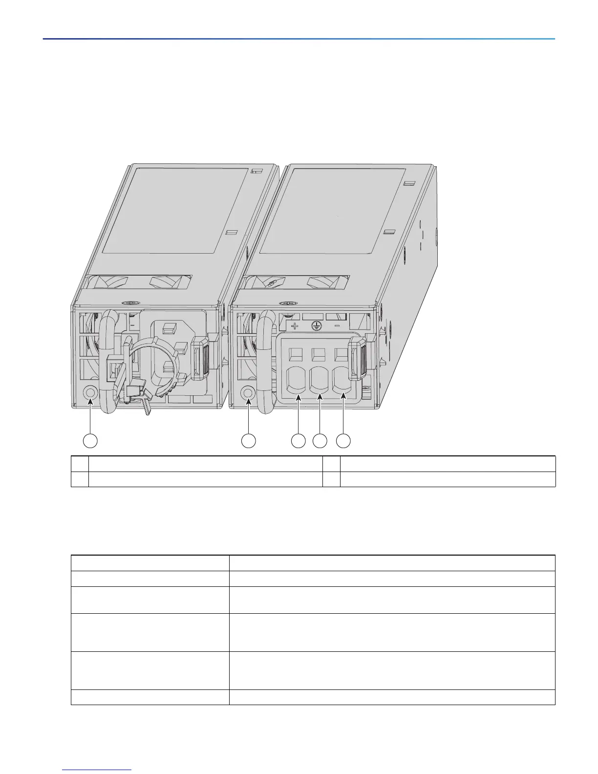
Figure 7 shows both the removable AC (on the left) and DC (on the right) power supplies for the ASA 5545-X and
ASA 5555-X.
Figure 7 AC Power Supply and DC Power Supply
Table 1 describes the power supply indicator. The function of the indicator is the same for both the AC and DC
power supplies.
1 Power supply indicator 2 DC power supply positive connection
3 DC power supply neutral connection 4 DC power supply negative connection
Table 1 AC and DC Power Supply Indicator
Indicator Color and State Description
Solid green Power output is on and within the normal operating range.
Blinking green, at the rate of one
blink per second
Input power that is within the normal operating range is being supplied, but
the Standby switch is in the Standby position (that is, chassis is not On).
Solid amber A power-supply critical event has occurred, and the power supply has shut
down. The critical event can be temperature, voltage, current, or fan
operating outside the normal operating range.
Blinking amber, at the rate of one
blink per second
A power-supply warning event has occurred, but the power supply can
continue to operate. The warning event can be temperature, voltage,
current, or fan operating outside the normal operating range.
Off The power supply is shut down.
 Loading...