Maintenance and Upgrade Procedures for the ASA 5500-X
Install and Remove a Solid State Drive for a Services Module
Cisco ASA 5512-X, ASA 5515-X, ASA 5525-X, ASA 5545-X, and ASA 5555-X Hardware Installation Guide
68
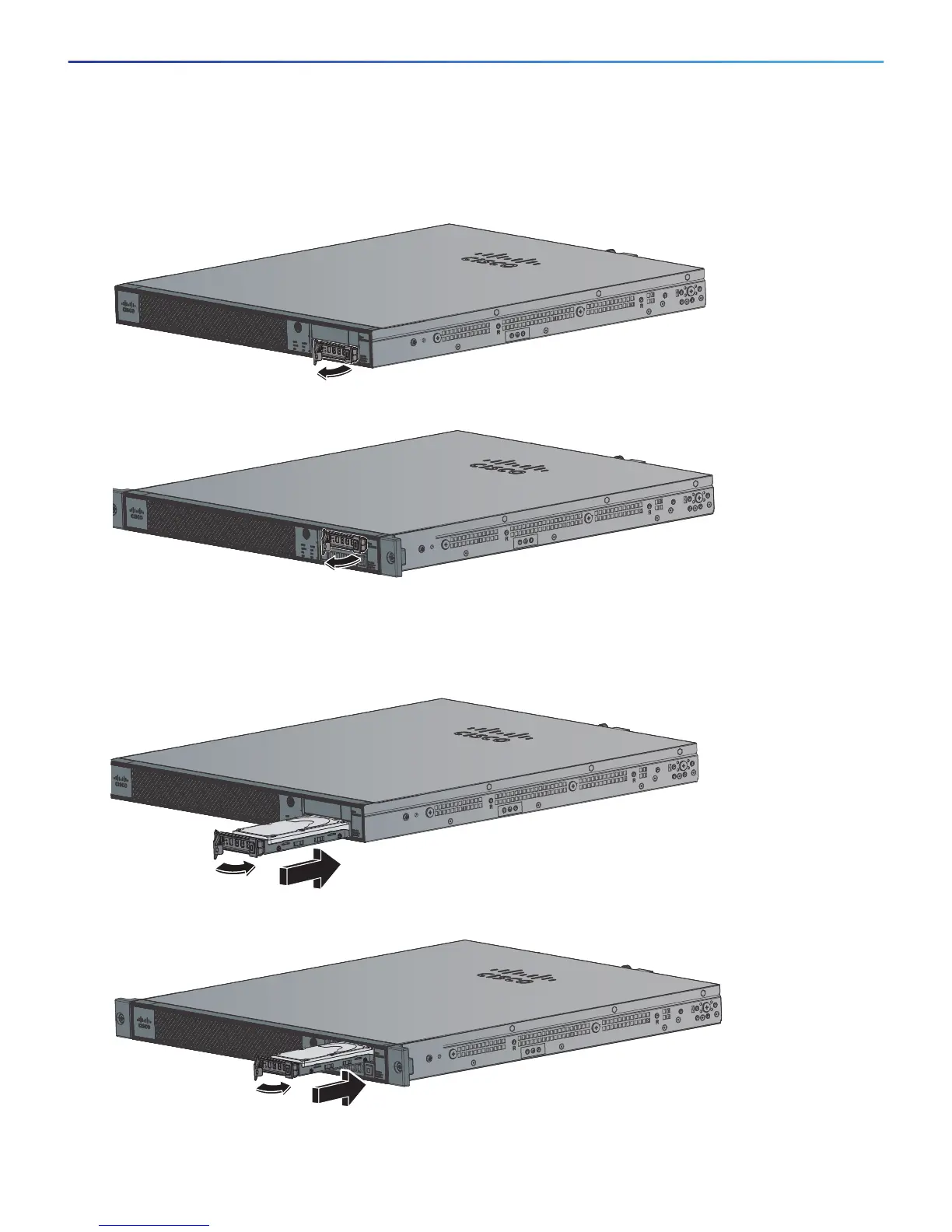
Figure 31 shows the ASA 5512/5515/5525-X models with one SSD. Figure 32 shows the ASA 5545/5555-X
with two SSDs.
Figure 31 Removing the SSD from the ASA 5512/5515/5525-X
Figure 32 Removing an SSD from the ASA 5545-X and ASA 5555-X
2. To install an SSD, on the front panel of the chassis, line up the SSD carrier with the SSD bay and push it in until
it is seated. Push the locking lever into place.
Figure 33 shows the ASA 5512/5515/5525-X models, while Figure 34 shows the ASA 5545/5555-X models.
Figure 33 Installing an SSD in the ASA 5512/5515/5525-X
Figure 34 Installing an SSD in the ASA 5545-X and ASA 5555-X