4-22
Cisco ASA 5585-X Adaptive Security Appliance Hardware Installation Guide
OL-22567-02
Chapter 4 Maintenance and Upgrade Procedures
Removing and Installing the Power Supply Module
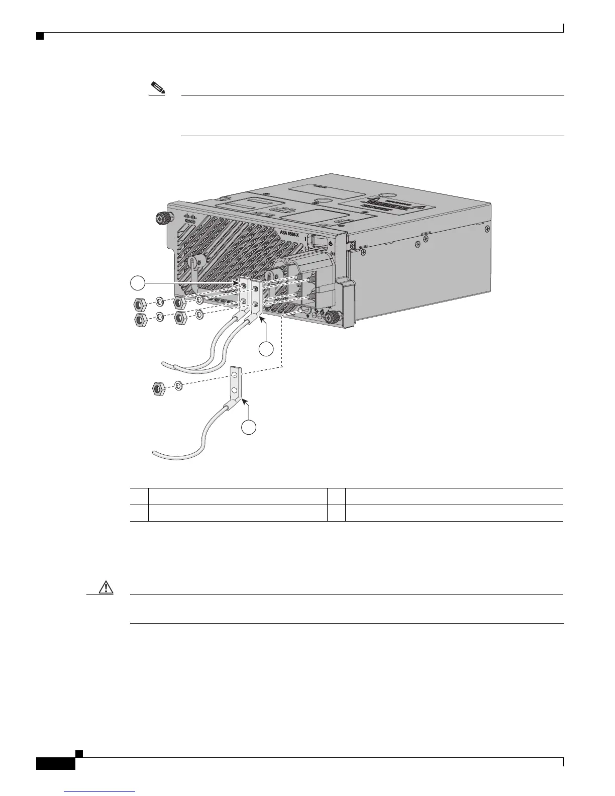
Note The terminal block on the 1150 W DC-input power supply is labeled negative (–)—that is,
the two left-side posts—and positive (+)—the two right side posts. The ground post is
located on the DC-input power supply faceplate, separate from the terminal block.
Figure 4-18 Attaching the Source DC Cables to the Power Supply Module
Step 9
Route the two source DC cables out of the terminal block, position the terminal block cover over the
terminal block, and snap the cover into place (Figure 4-19 on page 4-23). Make sure that both the top
and the bottom clips on the terminal block cover have fully engaged the tabs on the terminal block.
Caution To prevent short circuit or shock hazard after wiring the DC-input power supply, you must re-install the
terminal block cover.
1 Source DC negative (–) cable 2 Source DC positive (+) cable
3 Source DC ground cable
3
2
1
334529

 Loading...