4-23
Cisco ASA 5585-X Adaptive Security Appliance Hardware Installation Guide
OL-22567-02
Chapter 4 Maintenance and Upgrade Procedures
Removing and Installing the Power Supply Module
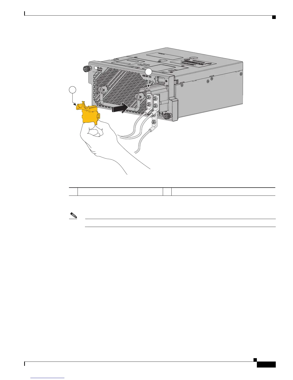
Figure 4-19 Reinstalling the Terminal Block Cover
Step 10
Repeat Steps 2 through 9 to connect power to the second power-supply module.
Note You must have two DC power-supply modules installed at all times.
Step 11 Remove any safety flag and lockout devices, or any tape, from the source DC circuit breaker
switch handle.
Step 12 Verify that the power cable ends at the power source are connected.
Step 13 Restart power by moving the circuit breaker switch handle to the on (!) position.
Step 14 If you powered off the appliance because you are removing and replacing both power supply modules,
power it back on. If you replaced only one power supply module, the power source is already on. You
can hot swap the module you are replacing and then turn its power back on.
1 Terminal block cover 2 Terminal block
2
1
334530

 Loading...