4-28
Cisco ASA 5585-X Adaptive Security Appliance Hardware Installation Guide
OL-22567-02
Chapter 4 Maintenance and Upgrade Procedures
Removing and Installing the Fan Module
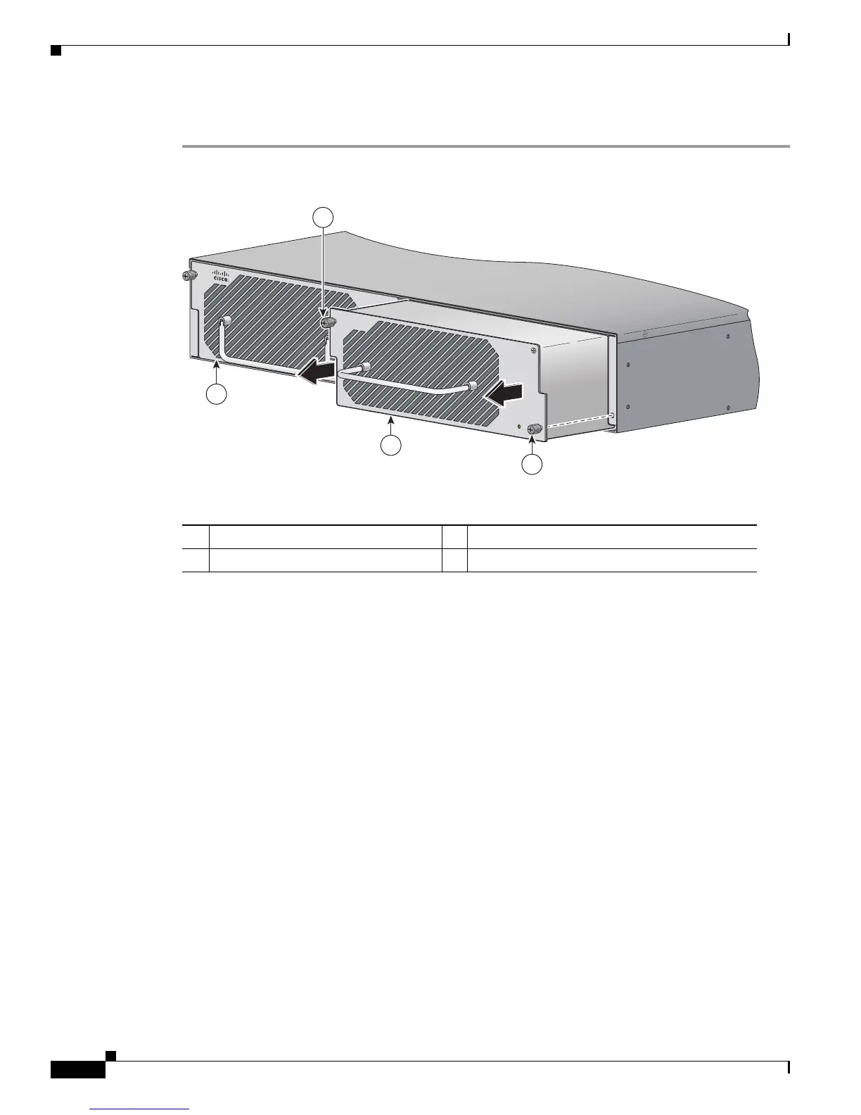
To remove and install a fan module, follow these steps:
Step 1 From the right-hand side of the back panel of the ASA 5585-X loosen the captive fan-module screws
until they release.
Step 2 Remove the fan module by grasping the handle and pulling the fan module away from the chassis.
1 Fan module and module handle 2 Fan module screws
3 Power supply module
Cisco ASA 1200W AC
100-240V
15.0/8.0.A
56/60Hz
IN
OK
FAN
OK
OUT
FAIL
Cisco-ASA-FAN
253909
2
1
2
3

 Loading...