4-27
Cisco ASA 5585-X Adaptive Security Appliance Hardware Installation Guide
OL-22567-02
Chapter 4 Maintenance and Upgrade Procedures
Removing and Installing the Fan Module
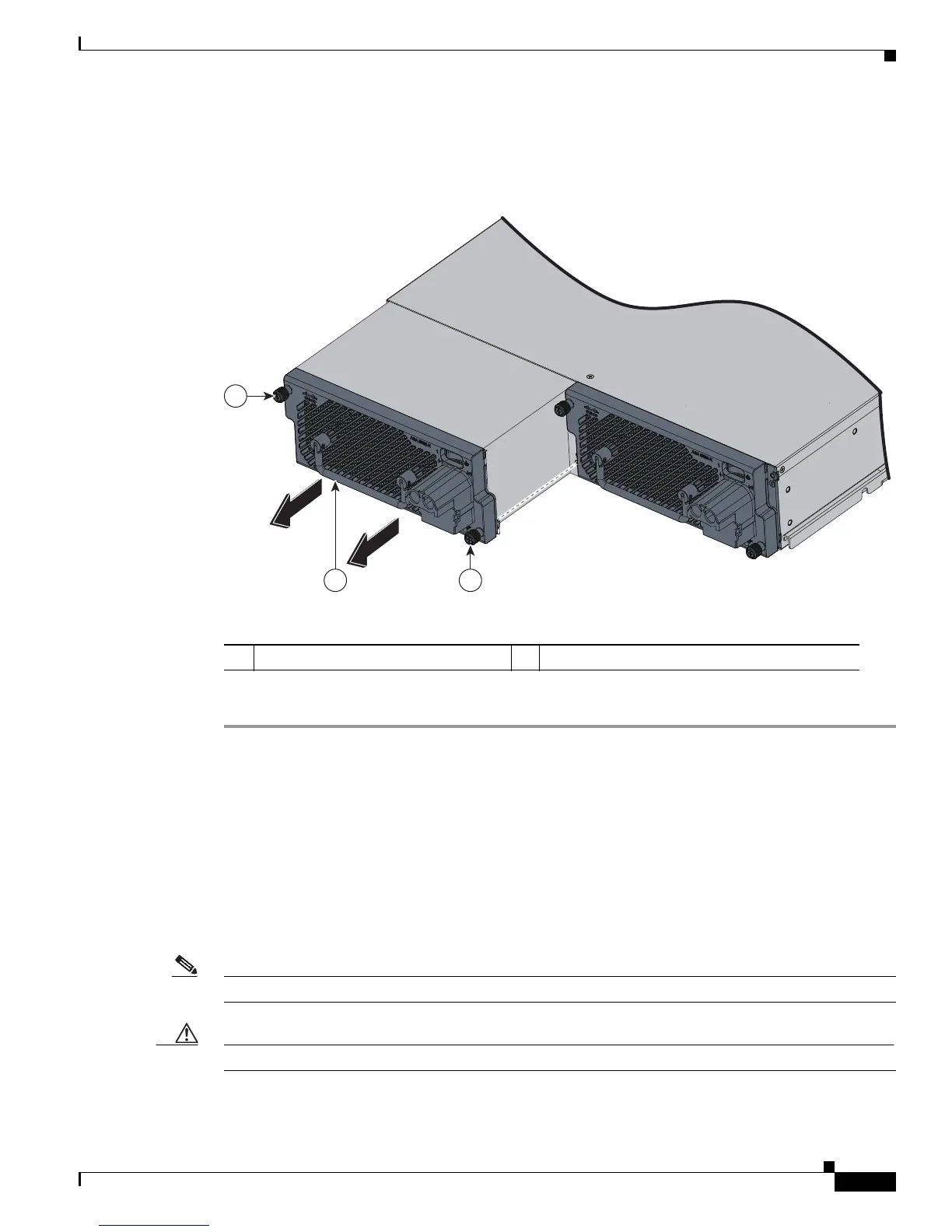
Step 7 On the back of the security appliance, loosen the captive screws from the power supply module
(Figure 4-23).
Figure 4-23 Removing the DC Power Supply Module
Step 8 Remove the power-supply module by grasping the handle and pulling the module out of the chassis.
Removing and Installing the Fan Module
The ASA 5585-X ships with one fan module and one power-supply module installed, except for the
ASA 5585-X SSP-60, which ships with two power-supply modules. You can replace the fan module in
the ASA 5585-X if necessary. The fan module is hot-pluggable. You can install or replace the fan module
without powering down the ASA 5585-X, as long as the power-supply module is active and functioning
correctly. To maintain airflow, both bays must be populated by either a power-supply module and a fan
module, or two power-supply modules.
Note A power-supply module is required for the system to operate.
Caution If you remove a power-supply or fan module, replace it immediately to prevent service disruption.
1 Power supply module screws 2 Power supply module and module handle
2 1
1
334516

 Loading...