4-3
Cisco ASA 5585-X Adaptive Security Appliance Hardware Installation Guide
OL-22567-02
Chapter 4 Maintenance and Upgrade Procedures
Removing and Installing SSPs
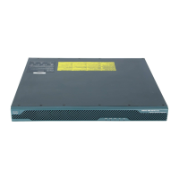
Step 8 Grasp the ejection levers at the left and right bottom of the module slot and pull them out.
Step 9 Grasp the sides of the module and pull it all the way out of the chassis.
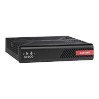
Step 10 Install the new module by lining it up with the slot. first ensuring the ejection levers are extended.
Step 11 Slide the module into the slot until it is seated and then push the ejection levers into place.
Step 12 Insert and tighten the captive screws.
Step 13 Reconnect the power cable to the ASA 5585-X.
Step 14 Power on the ASA 5585-X.
Step 15 Press Enter to confirm.
Step 16 Verify that the PWR indicator on the front panel is green.
1 Module 2 Ejection levers
1 Module 2 Ejection levers
PWR
BOOT
ALARM
ACT
VPN
PS1
HDD1
PS0
HDD0
USB
RESET
0
SFP1
SFP0
1
01234567
MGMT
0
1
AUX CONSOLE
253902
PWR
BOOT
ALARM
ACT
VPN
PS1
HDD1
PS0
HDD0
USB
RESET
0
SFP1
SFP0
101234567
MGMT
0
1
AUX CONSOLE
2
2
1
PWR
BOOT
ALARM
ACT
VPN
PS1
HDD1
PS0
HDD0
USB
RESET
0
SFP1
SFP0
1
01234567
MGMT
0
1
AUX CON SOLE
253903
PWR
BOOT
ALARM
ACT
VPN
PS1
HDD1
PS0
HDD0
USB
RESET
0
SFP1
SFP0
101234567
MGMT
0
1
AUX CONSOLE
2
2
1

 Loading...