16
Warning
Only trained and qualified personnel should be allowed to install, replace, or service this
equipment.
Statement 1030
Caution To comply with the Telcordia GR-1089 Network Equipment Building Systems (NEBS)
standard for electromagnetic compatibility and safety, connect the Ethernet cables only to
intrabuilding or nonexposed wiring or cabling.
Note The grounding architecture of this product is DC-isolated (DC-I)
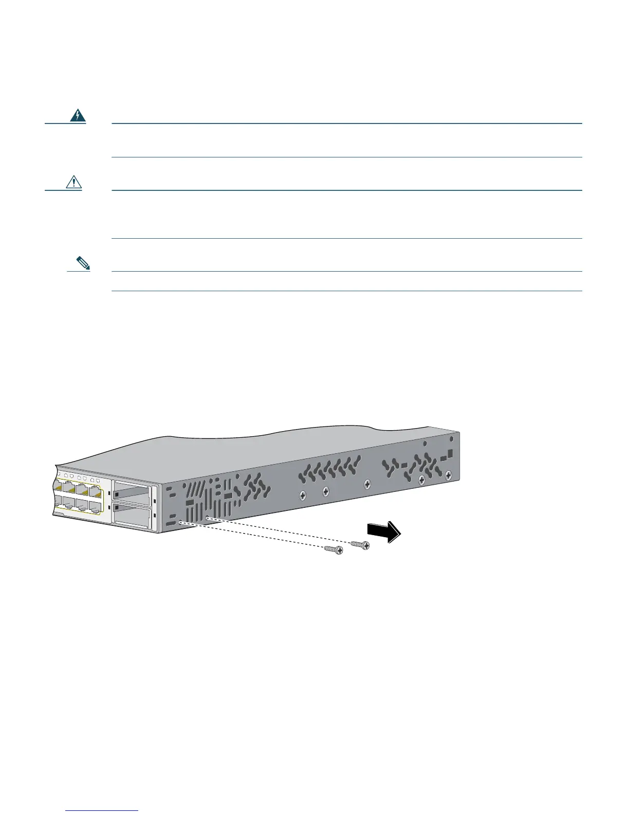
Before Attaching the Brackets
To install the switch in a rack, you must first remove the screws from the switch chassis so that the
mounting brackets can be attached. For attachment at the front-mounting position, remove two
Phillips truss-head screws from the switch side panels. For attachment at the mid-mounting position,
remove one screw. For attachment at the rear-mounting position, remove two screws.
157633
49
51
X
2-1
X
2-2
50
52
41
42
43
44
45
46
47
48
47X
48X
Catalyst 3750-E
SERIES
PoE-48