Chapter 1 Product Overview
Switch Components
1-10
Cisco Catalyst 4900M Switch Installation Guide
78-18350-01
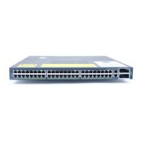
The LEDs on the front and rear panel of the Catalyst 4900M switch (see
Figure 1-5 and Figure 1-6 ) provide status information as follows:
• System LED indicates the operating state of the Catalyst 4900M switch.
• PS1 LED indicates the internal power supply status.
• PS2 LED indicates the internal power supply status.
• FAN LED indicates the fan tray status.
• A link status LED is below the 10-GB uplink ports.
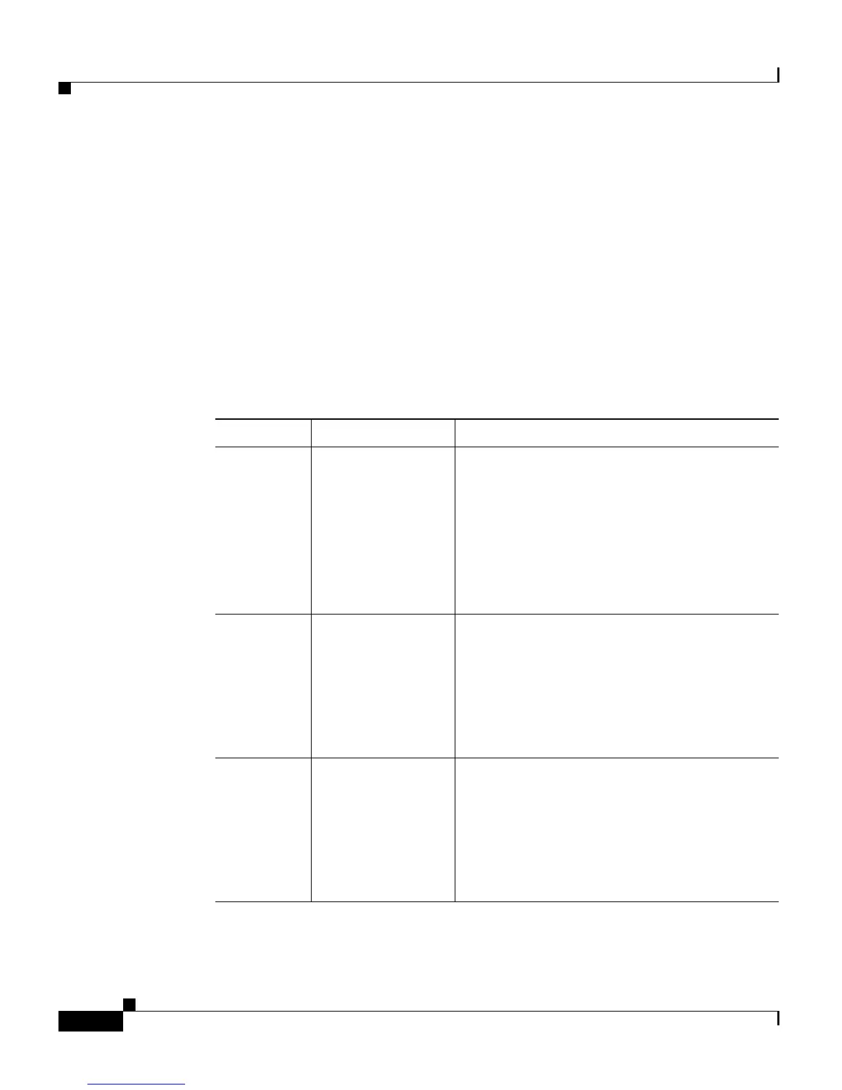
A description of the LED functions is provided in Table 1-1.
Ta b l e 1-1 LED Descriptions
LED Color or State Description
System
(front)
Green
Red
Flashing
Yellow
Off
At startup, the Catalyst 4900M performs a
series of diagnostic tests:
All tests pass
A test other than an individual port test fails
System boot or diagnostic tests in progress
System is in rommon mode or a power supply
has failed
Switch is disabled
CON
(rear)
Green
Off
10/100 BASE-T console port is in link-up
state
10/100 BASE-T console port is in link-down
state or not connected
There are no blinking, red, or yellow states
for this port
MGT
(rear)
Green
Off
10/100/1000BASE-T Management port is in
link-up state
10/100/1000BASE-T Management port is in
link-down state or not connected
There are no blinking, red, or yellow states
for this port