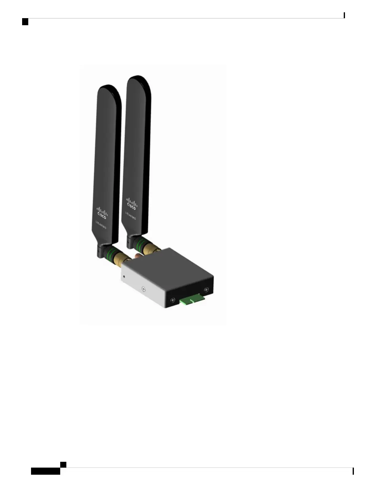
Figure 12: LTE Pluggable Module (With Antennas)
Installing a PIM
The modular cellular modem pluggable module's Remove and Replace options follow.
The IR1800 may have a blank plate covering the pluggable module slot. If it exists, remove it prior to installing
the cellular modem module. The following steps show the LTE pluggable module, however, they apply to other
modules as well.
Cisco Catalyst IR1800 Rugged Series Router Hardware Installation Guide
46
Pluggable Interface Modules
Installing a PIM