• The duration of each flash (LED off time) will be as follows:
• LED off time (in each flash) ~ 0.5 seconds.
• “Interim” LED on (between 2 LED offs) ~ 0.5 seconds
• If a member unit is removed from the stack, its system LED will continue to flash according to
above definition.
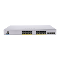
The following are per port LEDs:
• LINK/ACT—(Green) Located on the left of each port. The LED lights steady when a link between the
corresponding port and another device is detected, and flashes when the port is passing traffic.
• SFP+ (if present)—(Green) Located on the right of a 10G port. The LED lights steady when a connection
is made through the shared port, and flashes when the port is passing traffic.
• XG—(Green) Located on the right of a 10G port. The LED lights steady when another device is connected
to the port, is powered on, and a 10 Gbps link is established between the devices. When the LED is off,
the connection speed is under 10 Gbps or nothing is cabled to the port.
• Gigabit—(Green) Located on the right of the 1G port. The LED lights steady when another device is
connected to the port, is powered on, and a 1000 Mbps link is established between the devices. When
the LED is off, the connection speed is under 1000 Mbps or nothing is cabled to the port. (This feature
is only available on certain models).
• PoE (if present)—(Amber) Located on the right of the port. The LED lights steady when power is being
supplied to a device attached to the corresponding port. (This feature is only available on certain models).
Configuring Switches
The switch can be accessed and managed over your IP network using the web-based interface, or by using
the switch’s command-line interface through the console port. Using the console port requires advanced user
skills and is only supported on certain models.
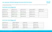
The following table shows the default settings used when configuring your switch for the first time.
Default ValueParameter
ciscoUsername
ciscoPassword
192.168.1.254LAN IP
Configuring Your Switch Using the Web-based Interface
To access the switch with a web-based interface, you must know the IP address that the switch is using. The
switch uses the factory default IP address of 192.168.1.254, with a subnet of /24. When the switch is using
the factory default IP address, the System LED flashes continuously. When the switch is using a DHCP
server-assigned IP address or an administrator has configured a static IP address, the System LED is a steady
green (DHCP is enabled by default).
Get To Know Your Switch
11
Get To Know Your Switch
Configuring Switches
 Loading...